Hi everyone, i'm making a basic arduino pinball machine. I am using large servos as the flappers.
I have uploaded the code, but no matter what I do, for some reason, whatever button I press, the servos flip up a few degrees then down again. Why is this? Please help (the code is below).
// Pinball code v0.1.0 by Jacob Jones 2014 #include <Servo.h>
// Here we are associating a keyword with a pin-number #define sright 6 #define sleft 5
Servo servoright;
Servo servoleft;
// Here we are creating two variables for the state of each switch
int buttonState = 0;
int buttonState2 = 0;
void setup()
{
int buttonState = 0;
int buttonState2 = 0;
guys - it sort of works - but when I press either button, both servos flap, and also they don't do it fast enough - even though I have set a delay time of 100, it takes more than 5 seconds for the servos to go down again. Any suggestions on how to solve these problems?
AWOL:
How is the switch wired?
You're not using the free, built-in pullups.
What are the free built in pull-ups ? I am a serious noob and this is my first attempt at writing code.
Th wiring is that one pin of each switch is connected to ground and to a digital pin, and the other to power
Here it is - sorry about not doing the correct thing
// Pinball code v0.1.0 by Jacob Jones 2014
#include <Servo.h>
// Here we are associating a keyword with a pin-number
#define sright 6
#define sleft 5
Servo servoright;
Servo servoleft;
// Here we are creating two variables for the state of each switch
int buttonState = 0;
int buttonState2 = 0;
void setup()
{
int buttonState = 0;
int buttonState2 = 0;
pinMode(sleft, INPUT);
pinMode(sright, INPUT);
servoright.attach(4);
servoleft.attach(3);
}
void loop()
{
servoleft.write(90);
servoright.write(90);
// Serial.begin(115200);
//for purposes of debugging uncomment above
buttonState = digitalRead(sleft);
buttonState2 = digitalRead(sright);
delay(200);
if(buttonState==HIGH)
{
servoleft.write(165);
delay(100);
servoleft.write(90);
}
if(buttonState2 ==HIGH)
{
servoright.write(165);
delay(100);
servoright.write(90);
}
}
Th wiring is that one pin of each switch is connected to ground and to a digital pin, and the other to power
You need to draw yourself a sketch of that: you'll see that when the switch is closed, it will connect the power direct to the ground and BOOM.
Hence the need for a resistor on either the 5V side (so-called pullup) or the ground side (pulldown). But as pointed out, the processor has pullups built-in to save us farting around with extra components. They are turned on thus:
pinMode(x, INPUT_PULLUP);
When you use a pullup (either the internal or an externally wired one), the switch reads as high until pressed then it will be low; this is known as "active low".
CrossRoads:
Internal pullup resistors.
Enable them witj
pinMode (pinX, INPUT_PULLUP);
or
pinMode (pinX, INPUT);
digitalWrite (pinX, HIGH);
disable with
digitalWrite (pinX, LOW);
There no pulldowns.
Wire the switch between pin & Gnd. Pressing the switch pulls the pin Low, releasing it lets the pin get pulled high.
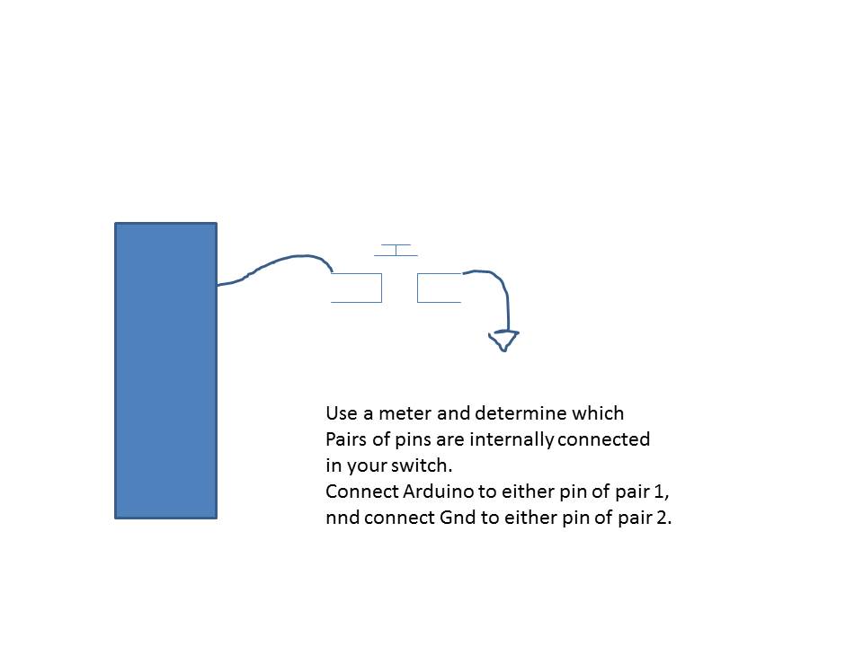
Thanks but when you say between pin and ground do you mean the switch with its 4 pins, do you mean ground and pin on either side of the switch, or on one pin?
I would suggest you add some comments to YOUR code so YOU can see what it does.
Than it MAY be more visible where are the logical errors AKA what does it do when no buttons are pushed?
BTW it is not good practice to activate anything / buttons using HIGH.
If you use internal pull-ups than you can reverse the logic - using active LOW.
Start here
void loop() // scan paddles (continually )
{
servoleft.write(90); // move left paddle 90 degrees - idle position
servoright.write(90); // move right paddle 90 degrees - idle position
// Serial.begin(115200);
//for purposes of debugging uncomment above
or use preprocessor directive
#ifdef DEBUG
Serial #endif
than #undef DEBUG when you done debugging
buttonState = digitalRead(sleft); // where is left paddle 0 idle 1 operated
buttonState2 = digitalRead(sright); // where is right paddle 0 idle 1 operated
// check the position
if( buttonState and buttonState2) // are they both at start / idle ?
//Serial yes
// Serial no
delay(200); // keep paddles in idle / start position operated for 200 ms
...
PS Do not just cut and paste above , it is not a code !
Ok quick update to everyone, I know for a fact that the servos are fast enough, as I ran a few tests without buttons etc, and they can easily get the distance within 200 milliseconds. So, I think that the problem is probably my wiring. Has anyone got a frizzing diagram or any diagram of how my switches should be wired?
Thanks
Thank you - sorry, it turned out to be my own incompetency when wiring up the switches rather than anything else.
I'm so happy - I didn't think I would be able to solve it and I would have failed my school project.