Hi guys,
I am new in here. I designed a dimmer for lamp and motor, but I have a problems.
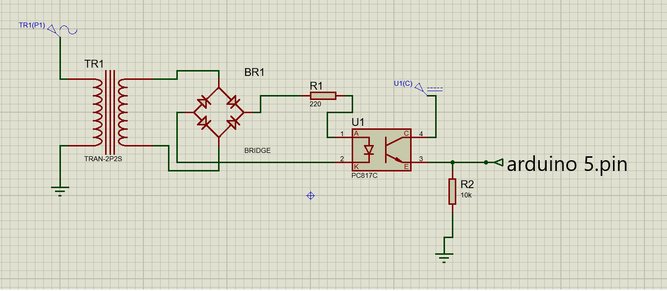
My arduino detects zero cross point ,and it gives energy arduino uno 5 pin .
Althought 5.pin is right, the triac cannot be triggered.
IF YOU HAVE AN APPLICATION, CAN YOU SHARE?
OR can you help me ?
We can but you need to help us first. You state you are detecting the zero cross and putting energy on the arduino pin 5. That tends to indicate the software is trying to fire the triac. We need a schematic, or hand drawing, not a frizzy picture. Post links to technical information on the hardware items in the circuit as well. Also let us know the voltages involved and if mains voltage do you have previous experience or somebody that can be with you while powering your project.

I testted that triac is right ,and normally if 5.pin is on, the triac is on.
Unfortunately, I do not try to work at that time.
Long shot, but...do you have an oscilloscope? That would make it a lot easier to troubleshoot your circuit.
Can you also please share the schematic of the circuit as you have built it, and not the images you used for inspiration found online?
Finally, please tell me that you didn't build the circuit as shown in that first Fritzing picture, with 230VAC on a breadboard. That's not exactly a safe way of working.
Ok, but as I understand, that's the part that probably works OK. How about the other part of the circuit?
No oscilloscope, I assume?
Your post was MOVED to its current location as it is more suitable.
Could you also take a few moments to Learn How To Use The Forum.
Other general help and troubleshooting advice can be found here.
It will help you get the best out of the forum in the future.
what triac are you using?
I use moc3042 and bt137 triac
So your circuit is 220v? Doesn’t look like MOC3042 is the right choice
MOC3042 is a zero-crossing type.
It cannot be used in dimmer (varying phase angle) applications.
It is for on/off applications.
The "zero-cross" ensures that it turns on only at '0vac'.
PE - [url]https://www.farnell.com/datasheets/2281302.pdf[/url]
1 Like
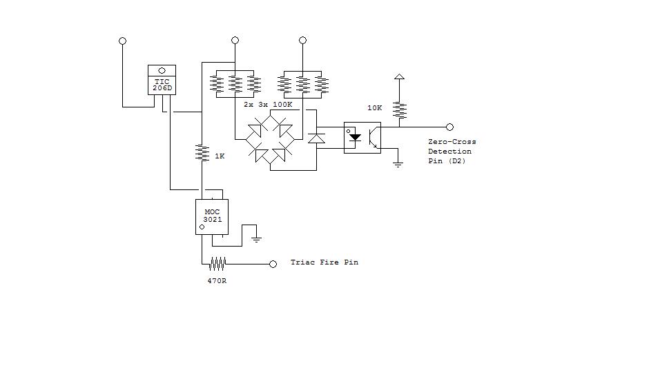
My Zero-cross detection works like this :

Using only 1/4 watt resistors.
And with a combination of a MOC3021 & TIC206D the whole thing looks like this :
As for code i can provide you with the following (as is, no modifications or support)
#include <TimerOne.h>

#define ZERO_X 2
#define AC_LOAD 3

volatile uint16_t dimming = 80;

volatile int i=0;
volatile bool zerocross;
uint8_t freqstep=9;

void setup(){
  Serial.begin(250000);

  pinMode(AC_LOAD, OUTPUT);
  pinMode(ZERO_X, INPUT);

  attachInterrupt(digitalPinToInterrupt(ZERO_X), ZeroCrossed, RISING);
  Timer1.initialize(freqstep);
  Timer1.attachInterrupt(DimCheck, freqstep);
  Serial.println("Started");

}
void loop()  {
  if (Serial.available()) dimming=(ExtractValue()*4);
}

uint16_t ExtractValue() {
  delay(1);
  byte msg;
  unsigned int command = 0;
  msg = (byte) Serial.read();
  while (msg != 10) {
    if ((msg>47) && (msg<58)) {
      command = command * 10;
      command = command + (msg - 48);
    }
    msg =(byte) Serial.read();
  }
  Serial.print("Dimming Level ");
  Serial.println(command,DEC);
  if ((command>20) && (command<255)) return command;
  return dimming/4;
}

void ZeroCrossed() {
  zerocross = true;
  i=0;
  digitalWrite(AC_LOAD, LOW);
}

void DimCheck() {
  if(zerocross == true) {
    if(i>=dimming) {
      digitalWrite(AC_LOAD, HIGH); // turn on light
      i=0;  // reset time step counter
      zerocross = false; //reset zero cross detection
    }
    else {
      i++; // increment time step counter
    }
  }
}
2 Likes
If you use a PC814 which is designed for this purpose, you do not need the bridge rectifier.
If you use INPUT_PULLUP instead of a 10k pullup, you do not need to feed as much current into the opto-coupler.

Thanks you, I change optocoupler and my zero cross detecter circuit
Tomorrow , First of all I will try new design
İnt a,deger,bekle;
int analogPin = A3;
void setup(){
pinMode(5,OUTPUT);
Serial.begin(9600);
attachInterrupt(1, kesme, RISING);
}
void kesme()
{
delayMicroseconds(bekle);
digitalWrite(5,HIGH);
delayMicroseconds(10);
digitalWrite(5,LOW);
}
void loop() {
deger = analogRead(analogPin);
a= map(deger,0,1023,0,128);
bekle= 75*a;
if(bekle<1050){
  bekle=1051;
  }
Serial.println(bekle);
delay(10);
  }
This topic was automatically closed 120 days after the last reply. New replies are no longer allowed.