My rover

Well here is my version of the arduino rover... which actually uses an iDuino, a Tamiya tracked vehicle kit (modded), a SRF-02 ultrasonic range finder, and some crappy code!

Here I will post some pics and videos, I won't post the code unless anyone is interested... its quite embarassing. :wink:

If you don't wish to view the progress pics and vids, here is the video at the end, of the latest version, doin its thing: - YouTube

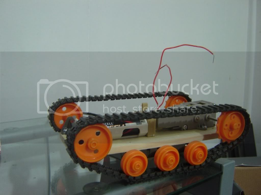
This pic was taken after I took the Tamiya tracked vehicle base out of the box and assembled it, haha look at it, what a POS! Only has one motor, so forward and backward... ordered a dual motor L/R independent gearbox, but it will be a while before I get that.

I put two breadboards together for lots of room, originally I planned on using the transistor + DPDT relay for motor direction and speed... that would have been pretty big if I ever set it up for the two motors.

Here is a video from that point of progress...

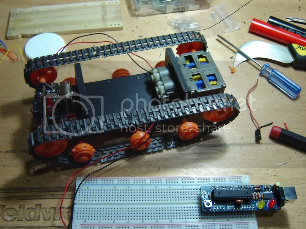
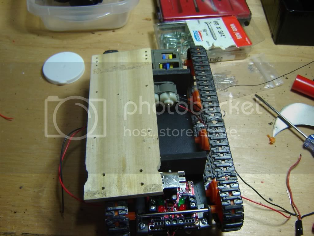
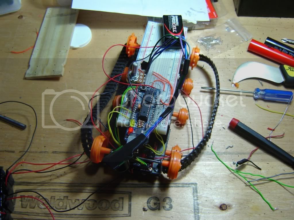
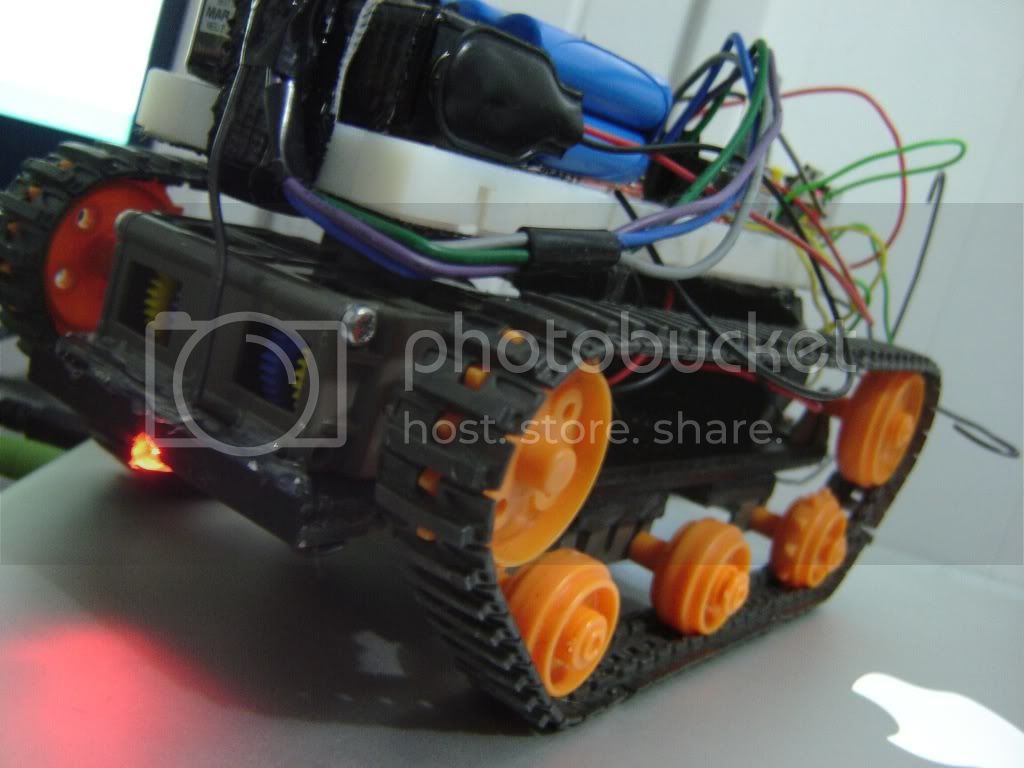
And heres a couple pictures after I mounted that stuff on the vehicle chassis, you can see the SRF-02 ultrasonic range finder laying on top in the first pic:


I did get the dual motor L/R independent gearbox installed in that chassis, and heres a video of that,
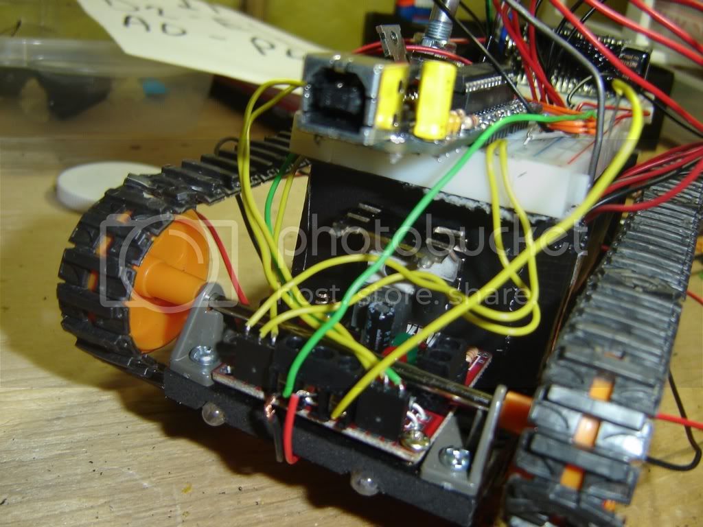
- YouTube - Ignore the music, youtube did something strange to the sound of that one, and it was all really distorted, so I randomly picked a song on the Youtube AudioSwap page... ugh... You will also notice a red square PCB on the back now, instead of the yellow DPDT relay, I decided to go with a L298 motor driver package instead because it was easy and readily available in 'kit form'.

Anyway I started having trouble with the tracks coming off on carpet when it was turning, and the chassis was limited by the fact that it was a simple piece of wood :smiley:

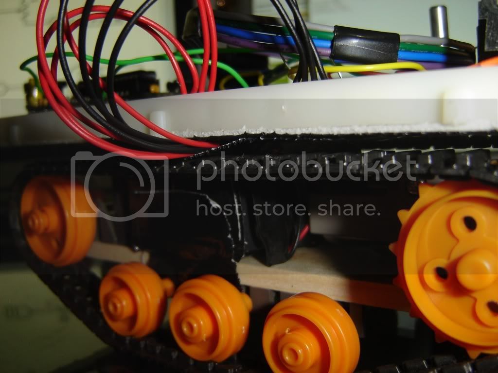
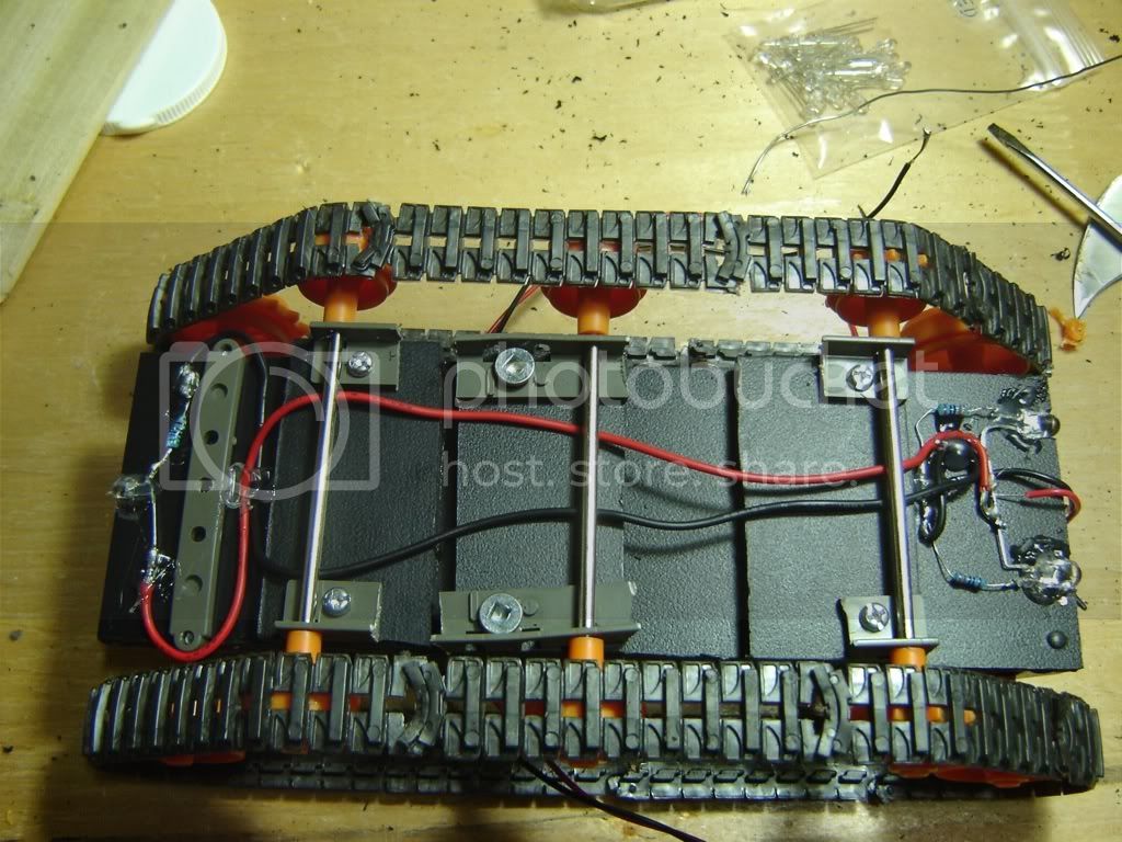
So I set to work rebuilding it from scratch, using some lightweight material I found at work, cant figure out if its closer to wood or plastic... but it works!


Heres the old chassis sitting on top of the new...

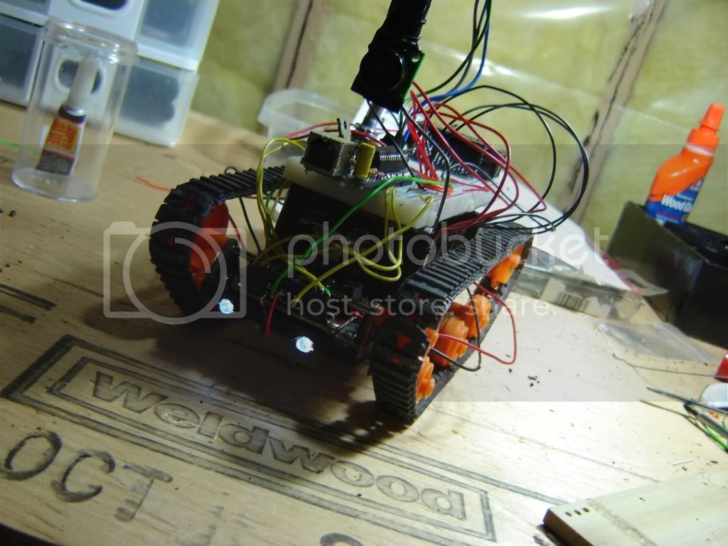
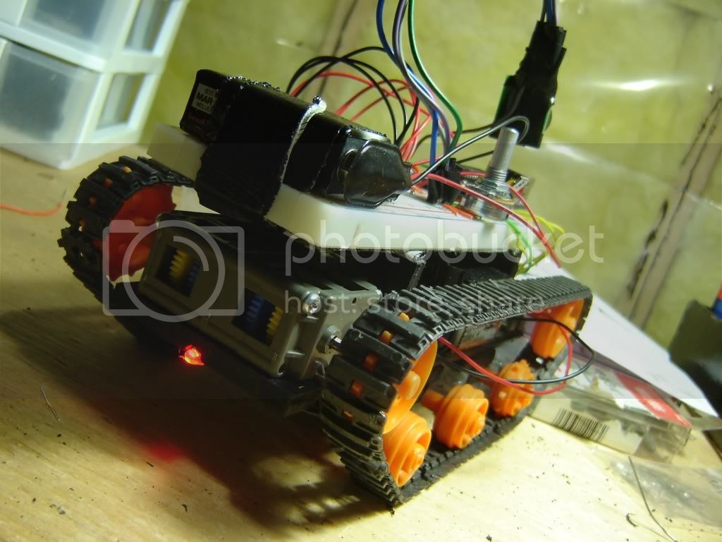
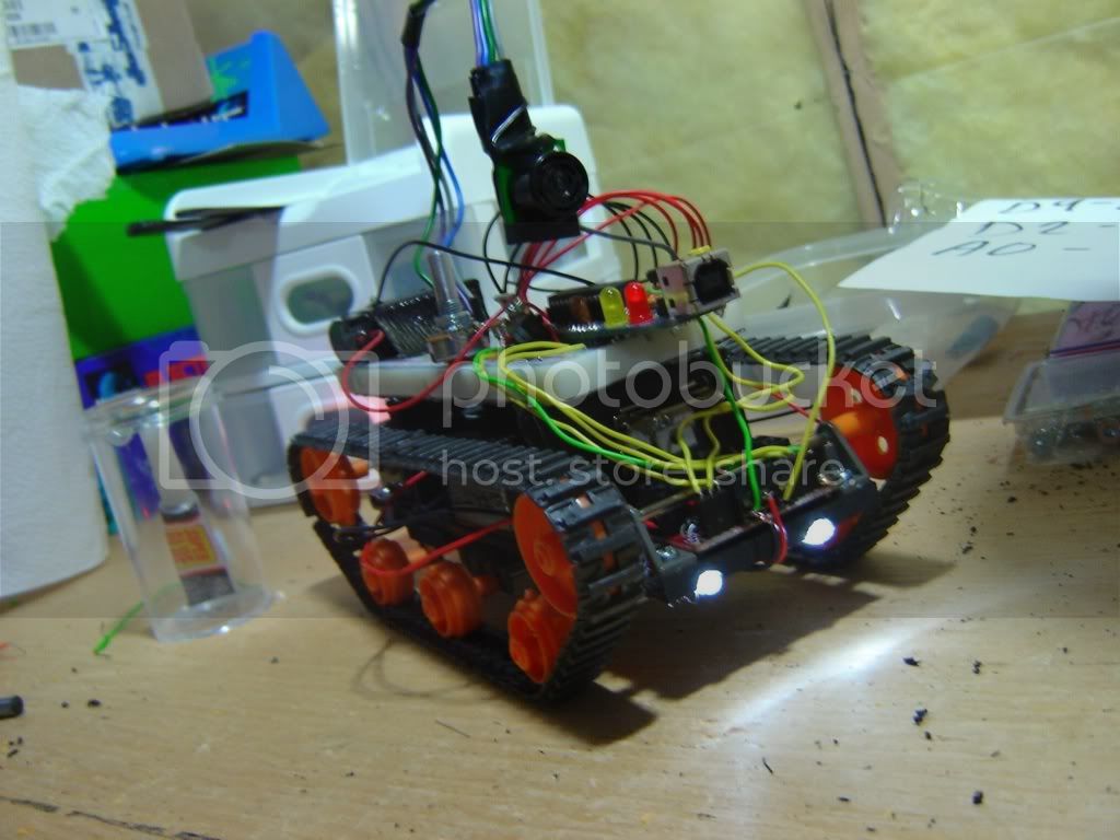
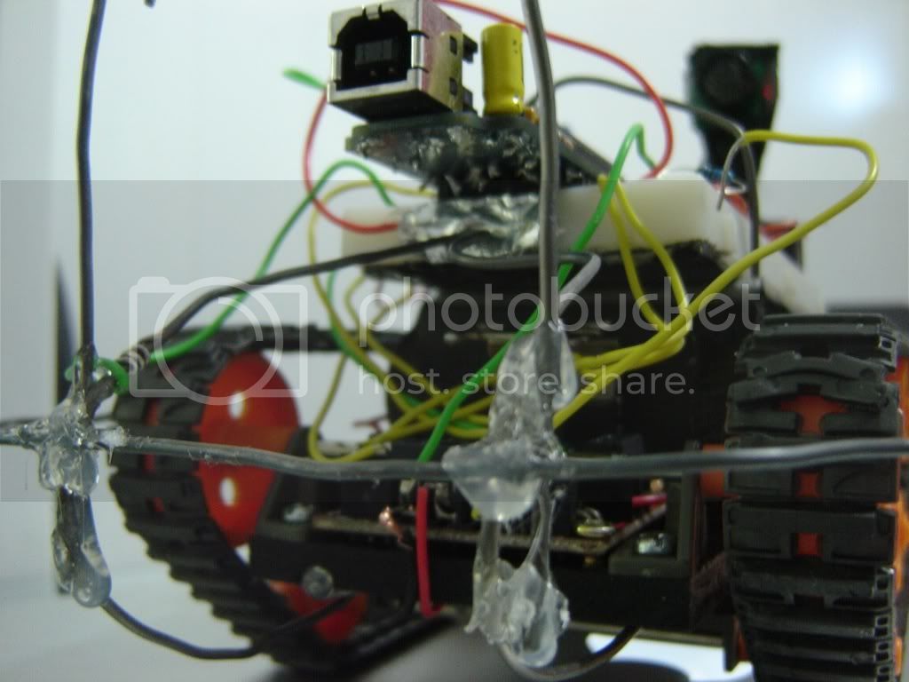
Okay, I don't like how I have the sensor mounted, and I have this problem where the ultrasonic sensor won't quite pick up objects at certain angles, and it will run into the wall and flip itself over. So I devised a way around this, by creating a terribly ugly bumper on the front, hot glued together, which when pressed on turns a pin HIGH, the vehicle then backs away and scans for a new path.

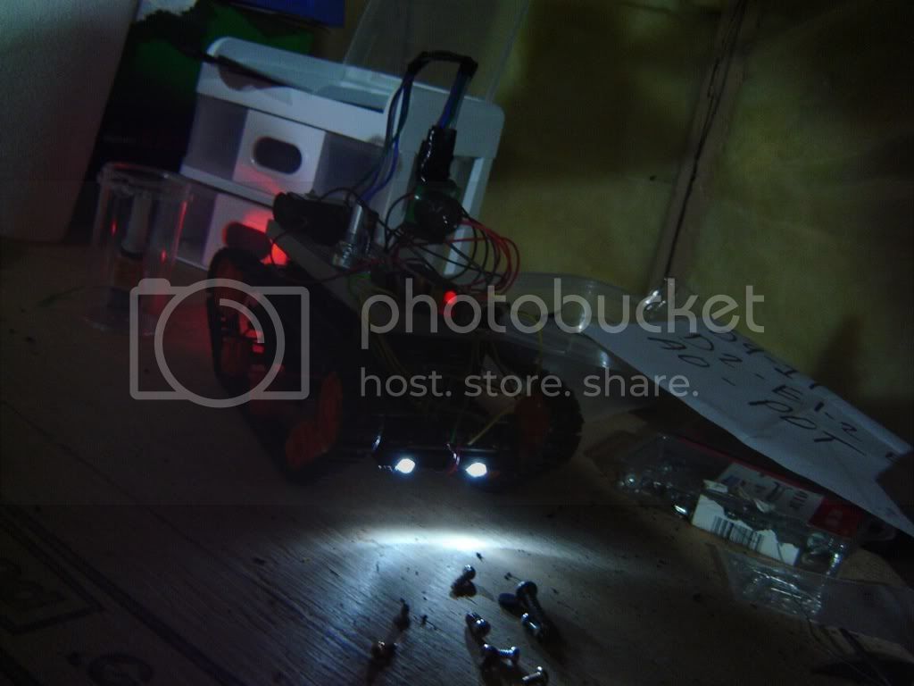
Heres some pics after that was added...

And finally, a video of the rover in its current state... don't mind the mess, im renovating that kitchen!

Future? Well, I plan on mounting some more range finders on it, possibly on a servo that can swivel the sensors around, or maybe even pan AND tilt... not sure. The whole reason it has the stupid bumper guard on it in the first place is because the ultrasonic range finder is stationary, and at angles it does not pick objects up properly... more sensors are definitely needed before I can remove the bumper guard switch....

Im open to criticism, this is my first real project... so I am not expecting much :stuck_out_tongue:

Thanks for checkin it out :wink:

Thought id just point out, right now the turns are random, because I have no way of knowing exactly how much im turning, or how fast, I have to just actively scan for a path while turning a pre determined direction. I just used a random number generation to decide which way it turns each time... ends up looking quite confused sometimes doesnt it :slight_smile:

Also, the crappy bump sensor requires quite a bit of force to set it off, so thats why it sat and grinded against stuff a few times... that only happens when it approaches objects on an angle...

Hi...

Cool to see heaps of photos of your progress.

I won't post the code unless anyone is interested... its quite embarassing. :wink:

FWIW I'd encourage you to post the code. While I don't always follow my own advice I think in general sharing some "suboptimal" code is better than no code and you never know when someone else can benefit from something you might think is a mess.

None of us here write code perfect and fully-formed in the first day of a project.

And, knowing some of the folks round here you might get some helpful suggestions on your code too.

--Phil.

#include <Wire.h> // SRF-02 being used in I2C mode...
#define address (0x00) // Had problems with putting the address straight into the code... ??

// Pins
int enablePin = 2;
int LeftMotorForward = 6;
int LeftMotorBackward = 3;
int RightMotorForward = 9;
int RightMotorBackward = 10;
int pot = 0;
int bumpSwitch = 12;
int override = 4; // So I can have the LEDs on without the motors engaging! LEDs are powered off the motor driver board.

// Vars
int TurnSpeed = 80;
int LookDelay = 500; // For the LookAround(); function which I don't really use anymore, because I cannot accurately measure how much I am turning... now Scan();
int results[5];
int look[4];
int bumperSensor = 0;

void setup()
{
  Wire.begin();
 // Serial.begin(9600);
  pinMode(enablePin, OUTPUT);
  pinMode(LeftMotorForward, OUTPUT);
  pinMode(LeftMotorBackward, OUTPUT);
  pinMode(RightMotorForward, OUTPUT);
  pinMode(RightMotorBackward, OUTPUT);
  pinMode(bumpSwitch, INPUT);
  pinMode(override, INPUT);
  pinMode(pot, INPUT); 
  digitalWrite(enablePin, HIGH);
  randomSeed(analogRead(2));
}

void loop()
{

  int result;
  result = doPing();
  int lowRange = result - 5;
  int highRange = result + 5;
  if (digitalRead(override) == HIGH) { 
    Stop(); 
  }
  else if (digitalRead(bumpSwitch) == HIGH || bumperSensor == 1) { 
    bumperSensor = 0; 
    Backward(); 
    delay(1000); 
    Scan(); 
  }
  else if (result == 0) { 
    Scan();
  }
  else if (result > 0 && result < 17) { 
    Scan();
    Forward();
  }
  else if (result >= 17) Forward();
  else { 
    Stop();
    //  delay(70);
  }
  delay(70);
}


int getPot() {
  int v;
  v = analogRead(pot);
  v /= 4;
  v = max(v, 50);
  v = min(v, 255);
  return v;
}

void Forward() {
  int offSet;
  offSet = getPot();
  offSet = offSet - 15;  // The motors don't turn at exactly the same speed
  digitalWrite(RightMotorBackward, LOW);
  digitalWrite(LeftMotorBackward, LOW);
  digitalWrite(enablePin, HIGH);
  analogWrite(LeftMotorForward, getPot());
  analogWrite(RightMotorForward, offSet);
}

void Backward() {
  digitalWrite(LeftMotorForward, LOW);
  digitalWrite(RightMotorForward, LOW);
  digitalWrite(enablePin, HIGH); 
  analogWrite(LeftMotorBackward, getPot());
  analogWrite(RightMotorBackward, getPot());
}
void Stop() {
  digitalWrite(LeftMotorForward, LOW);
  digitalWrite(LeftMotorBackward, LOW);
  digitalWrite(RightMotorForward, LOW);
  digitalWrite(RightMotorBackward, LOW);
  digitalWrite(enablePin, LOW);
}
void Left() {
  digitalWrite(LeftMotorForward, LOW);
  digitalWrite(LeftMotorBackward, LOW);
  digitalWrite(RightMotorForward, LOW);
  digitalWrite(RightMotorBackward, LOW);
  analogWrite(LeftMotorBackward, TurnSpeed + 10);
  analogWrite(RightMotorForward, TurnSpeed);
}
void Right() {
  digitalWrite(LeftMotorForward, LOW);
  digitalWrite(LeftMotorBackward, LOW);
  digitalWrite(RightMotorForward, LOW);
  digitalWrite(RightMotorBackward, LOW);
  analogWrite(LeftMotorForward, TurnSpeed + 10);
  analogWrite(RightMotorBackward, TurnSpeed);
}
void LookAround() { // I don't really use this part of the code anymore, as I cannot accurately judge how far the vehicle will turn on various surfaces... see Scan();
  look[0] = doPing();
  Left();
  delay(LookDelay);
  look[1] = doPing();
  Right();
  delay(LookDelay);
  Right();
  delay(LookDelay);
  look[2] = doPing();
  Left();
  delay(LookDelay);
  if (digitalRead(bumpSwitch) == HIGH || bumperSensor == 1) {  // I wanted to catch the bump switch being thrown in all possible parts of the code...
    bumperSensor = 0; 
    Backward(); 
    delay(1000); 
    return; 
  }
  else if (look[1] > look[0]) { 
    Left(); 
    delay(LookDelay); 
    Forward(); 
  }
  else if (look[2] > look[0]) { 
    Right(); 
    delay(LookDelay); 
    Forward(); 
  }
  else { 
    Left(); 
    delay(LookDelay * 2); 
    Forward(); 
  }
}

void Scan() { // The left or right decision is by random.... until I have a sensor that swivels to find the clearest path, this is the best way I can think of to navigate 
  int randNumber = random(0, 21);
  int i = 0;
  look[0] = doPing();
  int target = look[0] + 12;
  if (digitalRead(bumpSwitch) == HIGH || bumperSensor == 1) { bumperSensor = 0;  Backward(); delay(1000); return; } // I wanted to catch the bump switch being thrown in all possible parts of the code...
  while (doPing() < target) { 
    if (randNumber > 10 && i < 20) { Left(); i++; }
    else if (i < 20) { Right(); i++; }
    else { return; }
      }
}

int doPing() { // The SRF-02 is being used in I2C mode.
  int result = 0;
  Wire.beginTransmission(0x70);
  Wire.send(address);
  Wire.send(0x50);
  Wire.endTransmission();
  Wire.beginTransmission(0x70);
  Wire.send(0x02);
  Wire.endTransmission();
  Wire.requestFrom(0x70, 2);
  delay(70);
  while (Wire.available() < 2 )   {
  }
  result = Wire.receive() * 256;
  result = result + Wire.receive();   // Gives me a reading in inches from the SRF-02

  //for(int i=0; i<2; i++) { results[i] = results[i + 1]; }
  results[5] = results[4];
  results[4] = results[3];
  results[3] = results[2]; // This is for averaging the sensor reading...it was really jumpy with just the raw reading running through the code...
  results[2] = results[1];
  results[1] = results[0];
  results[0] = result;   // I had problems doing this in a loop, and in frustration I gave up and did it line by line...

  result = 0;
  for(int i=0;i<5; i++) { 
    result = result + results[i]; 
  }
  result = result / 5; // Average
  
  if (digitalRead(bumpSwitch) == HIGH) { 
    bumperSensor = 1;  // I wanted to catch the bump switch being thrown in all possible parts of the code...
    return result; 
  }
  return result;
}

Very nice project.

No reason to be shy about your code, it obviously works very well!

Here are some suggestions that I hope are helpful.

Try to give your variables names that reflect their purpose, for example
Renaming int result to int pingResult or just ping would make the reference later in the code clearer:
else if (result > 0 && result < 17) {
becomes:
else if (ping > 0 && ping < 17) {

You may also want to define some meaningful constants:
#define OBSTACLE_DETECTED 17

So your expression becomes:
else if (ping > 0 && ping < OBSTACLE_ DETECTED) {

also, you don't need the ping > 0 check (assuming the value returned from doPing is not negative)

so the code could look like this:
else if (ping == 0) {
Scan();
}
else if ( ping < OBSTACLE_ DETECTED) { // zero would be detected above
Scan();
Forward();
}
else if (ping >= OBSTACLE_ DETECTED){
Forward();
}
else {
Stop();
}

Thanks mem,

I see your point about the variables, I will make a point to start naming them better

think I had the check for result > 0 there before I added the result == 0 check before that. Definitely could clean the code up a lot though, thanks for pointing that out!

Today I added a wii nunchuck controller onto the I2C bus and added some code mostly from the playground to grab the accelerometer data from the nunchuck. I am only using one of the 3 axis, to detect when the rover rolls over. Sometimes it rides up on something and tips, and then it sits there and runs the tracks on the ground, catching wires and ripping things apart. So if the code detects an abnormal amount of tilt on the x axis it stops the motors...

heres a quick vid: - YouTube

Thanks for lookin :slight_smile:

Update: I updated it to actually detect forward and backward tilt as well, I will post the code shortly.

here is the code with the wii nunchuck stuff added in, also made some changes based on mem's feedback

http://reactorfx.com/steve/Rover2_1.pde

[snip]

Wow, someone actually took my advice. :slight_smile:

Here are some suggestions that I hope are helpful.

Hee, hee, told you so, steveo1984... :smiley:

I am only using one of the 3 axis, to detect when the rover rolls over. Sometimes it rides up on something and tips, and then it sits there and runs the tracks on the ground, catching wires and ripping things apart. So if the code detects an abnormal amount of tilt on the x axis it stops the motors...

That's a nifty solution...

Thanks for sharing.

--Phil.

You should try adding the ping sensor. Might make things a little more difficult though.
I have the same platform for one of my robots but i founds it is hard to use any thing else than the two geared motors
great project!

You should try adding the ping sensor. Might make things a little more difficult though.
I have the same platform for one of my robots but i founds it is hard to use any thing else than the two geared motors
great project!

I am not sure what you mean by adding the ping sensor?

Anyway here is an update, I ditched the tracked base, it was a mere toy and impossible to work with. Finding no cost effective alternative for tracks, I went with something simple. 2 GM3 gear motors with wheels and a pair of tactile sensors from Solarbotics, a bigger piece of sintra, and a swivel caster. Here are a few pics,


And as usual from me, some videos...

This one is with the digital camera stuck to the front of the rover, notice the pieces of tape in the pictures above, thats why they were there.

Having problems with that caster on the front, it doesnt like to sit straight, so it always causes the vehicle to track left or right as it isnt heavy enough. I will have to find a ball caster, lightweight.

Anyway, on the way from robotshop.ca I have two xBee transceivers, an I2C IR rangefinder, and a few other goodies. The IR rangefinder will be on a servo, for a "look around" feature. I recently picked up two StampDuinos and another iDuino from fundamental logic, my plan is to use one to create a 'base unit' for the rover. This base unit will have a 2 line LCD display, a joystick and a couple of buttons for menu navigation, and one of the xBee radios. The rover will obviously have the second xBee radio, this will not only enable me to remote control the vehicle directly (R/C mode), but also to manipulate variables and view realtime data on the rover via a simple menu system. Things like motor speed, rangefinder values and limits, the ability to turn on and off features or activate different modes of operation. Since I will be using a StampDuino for the base unit, I have a FTDI usb breakout board to program it, as an added bonus, I need only quickly change the TX/RX lines from the stampduino to the xBee directly, and it becomes possible to wirelessly update the program on the atmega168 which is on the rover, in the other arduino.

I will be building the maxstream circuit for the xBee radios, and possibly creating some printed circuit boards for myself, just to keep everything neat. I have always wanted to try out etching.

I will be sure to keep updating as I progress through this. Thanks for looking.

http://www.parallax.com/Store/Sensors/ObjectDetection/tabid/176/ProductID/92/List/1/Default.aspx?SortField=ProductName
This sensor.

http://www.parallax.com/Store/Sensors/ObjectDetection/tabid/176/ProductID/92/List/1/Default.aspx?SortField=ProductName
This sensor.

Mine was cheaper :stuck_out_tongue:

You see that black thing on the back, on the end of the spring whip? That is an ultrasonic sensor with an I2C interface, it just isn't the exact same one that you have linked. If you take a look at some of the code I have posted, you will see right away that I do use this sensor for object detection. Also as mentioned in my post above, I will be adding an infrared rangefinder on a servo at the front of the vehicle. So I will be utilizing both types of sensor at the same time.

The tactile sensors on the front are there because the ultrasonic sensor is highly sensitive to angles, so until I have the IR range finder swiveling to 'look around', the tactile sensors are the best way to avoid burning a motor or my motor driver out if something does get past the ultrasonic and it gets stuck up against something.

Here is some new code... still pretty messy. I added some time-decay variables for the tactile sensors and left/right turns. Otherwise most of it is the same.

The left and right turn count variables are there to keep the vehicle turning the same direction in a series of close together turns. Before, it was very random because I have no way of looking for a path without turning the vehicle, so it would often go back and forth and take a long time to get itself out of a corner, and was not too successful in finding paths out of tight areas. Now every time the vehicle turns, I increment the appropriate variable. Both of these variables are decreased every third cycle through the main loop. This translates to roughly 3-4 seconds. When Scan() is called now, it tests to see if the vehicle has been turning more left or more right recently, and continues turning that same direction. If both are equal (impossible, cant happen) or if both are zero, the decision is random. So basically the first turn in a sequence of turns is always random, the rest is at least a better attempt to follow a path. If the vehicle has been turning a lot, it sometimes takes up to 5 or 6 seconds for the turn variables to clear to zero, I have had to tweak the frequency of the decrement a bit and found this to be a good amount of time to shoot for. Any higher and it just keeps turning in circles :slight_smile:

As for the tactile sensors, if one of them stays tripped for too long, the vehicle will back off and call Scan(). The same type of time decay is implemented here, only every fifth cycle of the main loop on this one.

I didn't edit it before posting, and i've been messing around a lot, so don't be surprised if some of it is ugly. :wink:

http://reactorfx.com/steve/rover3/Rover3.pde

Hope you dont mind my rambling. :-X

maybe you can use a servo to get a 180 front view using your ultrasonic range finder... that way your rover can head in the right direction instead of guessing which way to go... ofcourse only as a suggestion

maybe you can use a servo to get a 180 front view using your ultrasonic range finder... that way your rover can head in the right direction instead of guessing which way to go... ofcourse only as a suggestion

Yup, mentioned that a few posts back. Since the ultrasonic is so highly sensitive to giving bad readings when its on an angle to something, I decided to add an IR rangefinder as a 180 degree front view while retaining the static ultrasonic sensor.

....The IR rangefinder will be on a servo, for a "look around" feature....

One thing I have yet to work out is how I will have the vehicle head in the desired direction once the 180 degree sensor swivel is implemented. Since I cannot currently judge how far the vehicle is turning, once I do find a clear path, I will need a way to have the vehicle turn until its pointing in that direction. I am open to suggestions... I dont have the components to do this yet but id like to start thinking about how to go about it.

Thanks for the suggestion big93 :slight_smile:


shes ugly but it works :stuck_out_tongue: now just waiting on a couple xBees, a servo and IR rangefinder...

is it just me or are friday nights not what they used to be ? ;D

Bit of an update... I got my xBee transceivers and I have tested them in a different project, working great. I am going to start implementing the wireless serial first between the computer and the rover, and later build a second arduino device to be the controller, with the LCD screen and all that on it. Bummer though my I2C-It IR rangefinder from solarbotics/hvwtech seems to be faulty, so I have to send that back and for now im stuck with the ultrasonic by itself.

Today though I am working on the ability to give 360 degrees of sensor readings, and also provide some useful tilt and auto levelling for the sensor platform. You see, every time the rover is going down a ramp or hits a little bump it sees the ground as an object to avoid. I have to work on the code a little bit, maybe even rewrite some major parts to avoid such heavy use of delay(). Then the auto levelling will work faster, right now its still very slow to react and it still gets bunk readings from the ground sometimes.

Here is a video of the auto levelling. - YouTube

I am working on the 360 degree view now also, however the sensor platform has to flip over so its upside down, which results in it pointing the other way, so one idea I had is if I could create 2 arrays with 360 values in each, in the x array I would have the pan value and the y array the tilt value for that corresponding 'degree'. That way I could just specify I want N degree and it would take care of where the tilt and pan have to be for that degree... not sure how well that would work or not but im going to find out :slight_smile:

Thanks for looking.

Okay here we go, got the 360 degree sensor platform operational, sounds like an unhealthy bubblejet printer :stuck_out_tongue:

I did it preset steps of 10 because I couldnt think of any other way, the arrays would have been enormous to do all 360 steps...

int panDegree[34] = {87,77,65,54,47,40,33,24,19,10,163,151,140,127,115,104,92,82,72,62,52,41,30,20,160,155,150,145,137,130,123,115,106,97};
int tiltDegree[34] = {19,19,19,19,19,19,19,19,19,19,172,172,172,172,172,172,172,172,172,172,172,172,172,172,19,19,19,19,19,19,19,19,19};

that is what allows it to flip over and (attempt, poorly) to keep going where it left off.

To me there is no clear way to do that stuff with math... if someone out there has any ideas on calculating angles id love to hear them... but I think I am just going to have to steer clear of complex math formulas for now lol. I am a mathematics failure. >:(