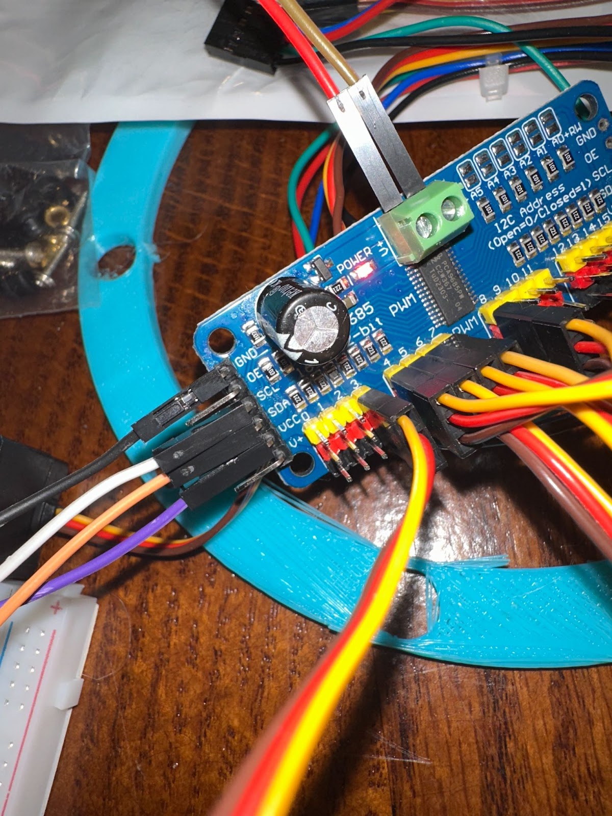
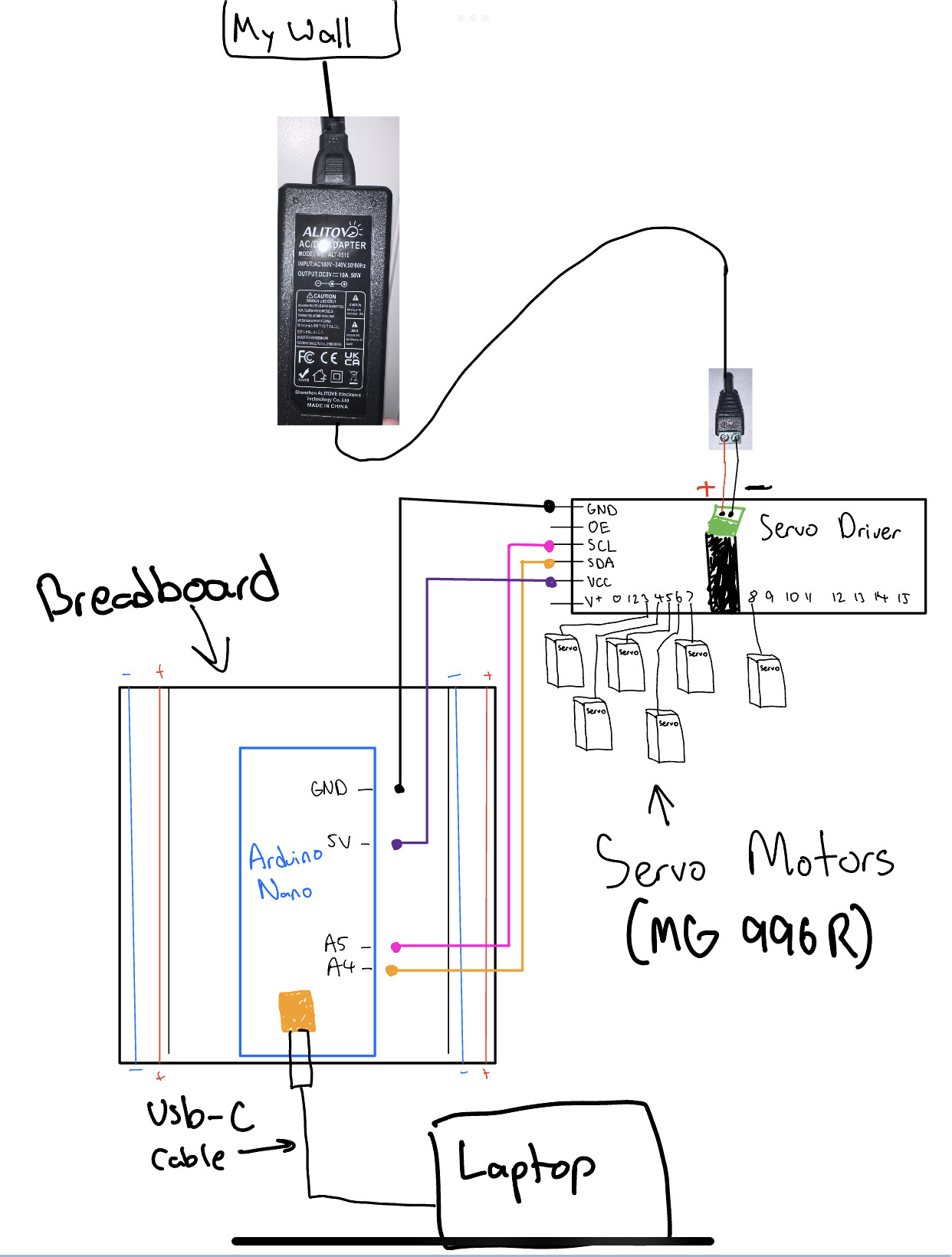
I am trying to hook up my Arduino Nano to my Adafruit 16-Channel 12-bit PWM/Servo Driver (PCA9685). I have a wire plugged into the wall that can draw 10A, and this is connected to the servo driver, so I know I have enough power for 6 servos (MG 996R). I am using a breadboard. I am powering my Arduino itself my plugging it into my laptop. Also, I know that my code is uploading to my Arduino because I tried the blinking thing in the Arduino IDE and I got my Arduino light to blink. I have connected my servo to my driver:
Driver Pin and Servo Pin connections
Gnd -> Gnd
Vcc -> 5v
SCL -> A5
SDA -> A4
(I used different color wires too so you could tell)
I am using ALITOVE AC/DC Adapter, model ALT-0510, which takes an input of AC 100–240V at 50/60Hz and provides a DC output of 5V at 10A (50W).
I am not sure why none of my servos are moving? Also, this is my first post here, I read how to post properly instructions, but if there is any further context I could provide please let me know! I really need the help haha!
Thank you for posting the code in code tags.
Pictures are pretty much useless, what we need are a picture of your hand drawn wiring. Also, consider simplifying. If it fails with a single servo that is easier to solve.
Check to see if you have 5V on the center pin of one of the servo connectors. You may have blown the reverse polarity MOSFET beside the big electrolytic. Those little SOT23s were only good for 4A. Adafruit switched to a beefier one in a TO-252 DPAK that was good for 20A+ ten years back because the little ones kept going pop. The clones haven't made the switch, by and large.
Sorry I cannot follow your wiring "can-of-worms", posting an annotated schematic would go a long way in solving your problem. Have you tried @JCA34F suggestion?
Unfortunately you have extended the supply with crappy Dpond signal wires between the screw terminals that can't carry more than 1Amp without melting or giving instability.
As @van_der_decken said, that clone board has a tiny weak mosfet, that you can bypass (if needed) by connecting servo power directly to the V+ pin.
Leo..
Thank you for responding! What do you mean by clone board, are you taling about the breadboard? Also, are you saying that the male to female wires I'm using are the wrong wires for the job? Is there a different set of wires I should buy off of amazon? Also, since eventually I will need to be powering 6 servos I would need to be able to power the driver to distribute that power, are there any cables you'd recommend I use that could transfer that power?
What I wrote seems clear enough to me. I told you what to check, why to check it and even told you where to obtain something that wouldn't suffer from the same problem.
It looks like two equivalent means to instantiate the object named pwm, given that the default i2c address is 0x40.
The explicit call with 0x40 might be preferable, as it makes clear where the code expects to find the device, and might make a person realize there are address jumpers on the PCA9685 that need to match.
A sentence from the Adafruit PCA9865 document... when using many servos, power may sag, so...
If you are driving a lot of servos from a power supply that dips a lot when the servos move, n * 100uF where n is the number of servos is a good place to start - eg 470uF or more for 5 servos
[edit] the document has HTML to TEXT mistakes... "<" means "less than" and ">" means "greater than"
I agree. I did not add the address for fear of being suspended for "hard coding"... heh... but all the library examples show an address in the instance thingy of 0x40, which is the default if no value is entered.
As mentioned, use a 5-6V 15 Ampere (minimum) power supply for 6xMG996R, and use heavy duty power wiring or a servo power distribution PCB rated for 15A.
I am confused, so are you saying that I should power all 6 servos by connecting them through the breadboard ad just have the power go through the power rails of the breadboard?