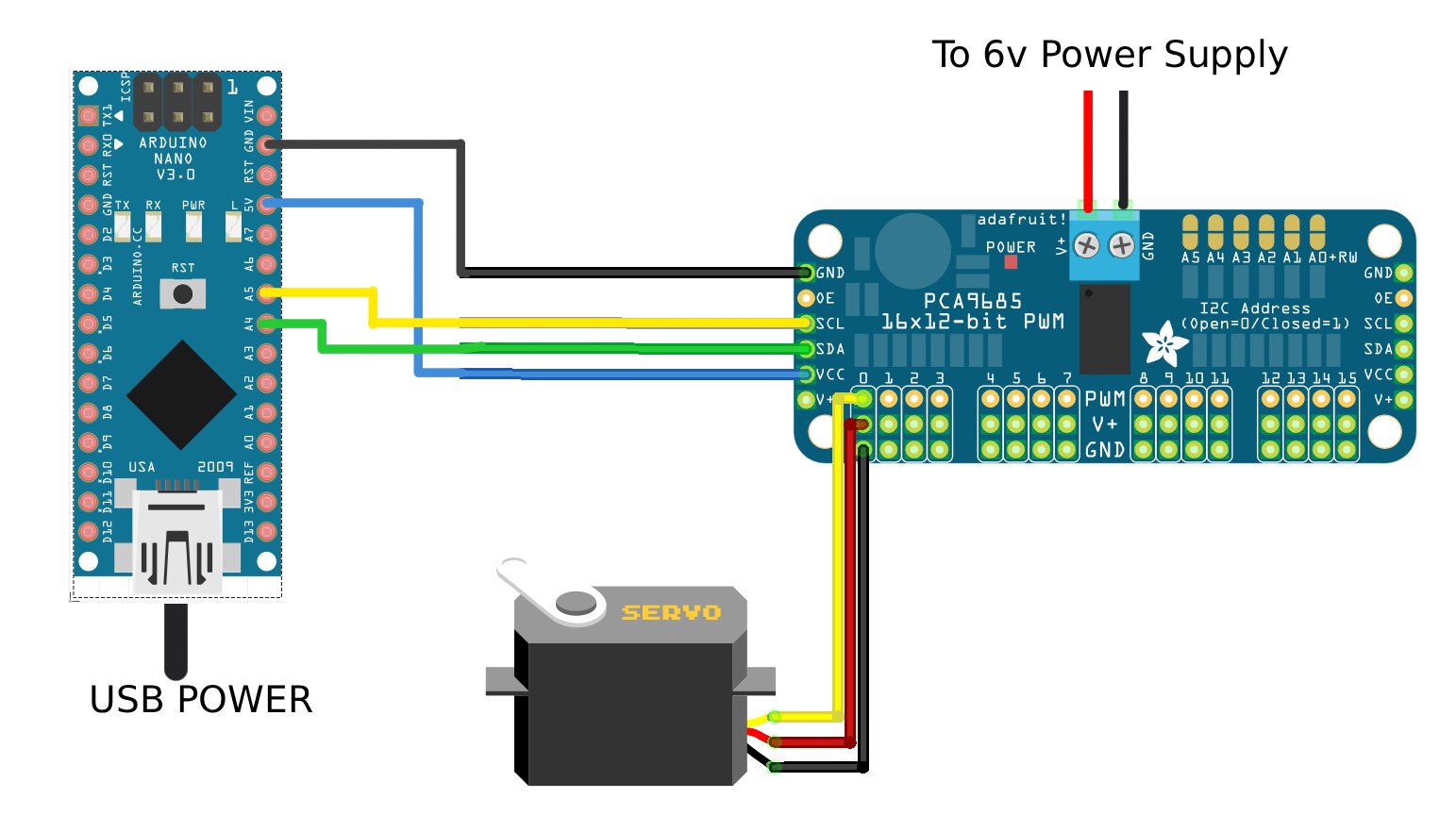
I am working on a project that involves controlling ~30 Miuzei MG90S micro servos. I have chosen a pair of PCA9685 servo driver boards to help address and power all these servos.
The problem I am having appears as this:
When running the example code "Adafruit PWM Servo Driver Library > Servo", the motors are to be swept one at a time.
Motors 2, 5, 9, 10 do not move at all on my board. Sometimes I can hear a faint whining from the servo.
Here is a copy of the example code I am using:
/***************************************************
  This is an example for our Adafruit 16-channel PWM & Servo driver
  Servo test - this will drive 8 servos, one after the other on the
  first 8 pins of the PCA9685

  Pick one up today in the adafruit shop!
  ------> http://www.adafruit.com/products/815

  These drivers use I2C to communicate, 2 pins are required to
  interface.

  Adafruit invests time and resources providing this open source code,
  please support Adafruit and open-source hardware by purchasing
  products from Adafruit!

  Written by Limor Fried/Ladyada for Adafruit Industries.
  BSD license, all text above must be included in any redistribution
 ****************************************************/

#include <Wire.h>
#include <Adafruit_PWMServoDriver.h>

// called this way, it uses the default address 0x40
Adafruit_PWMServoDriver pwm = Adafruit_PWMServoDriver();
// you can also call it with a different address you want
//Adafruit_PWMServoDriver pwm = Adafruit_PWMServoDriver(0x41);
// you can also call it with a different address and I2C interface
//Adafruit_PWMServoDriver pwm = Adafruit_PWMServoDriver(0x40, Wire);

// Depending on your servo make, the pulse width min and max may vary, you
// want these to be as small/large as possible without hitting the hard stop
// for max range. You'll have to tweak them as necessary to match the servos you
// have!
#define SERVOMIN  150 // This is the 'minimum' pulse length count (out of 4096)
#define SERVOMAX  600 // This is the 'maximum' pulse length count (out of 4096)
#define USMIN  500 // This is the rounded 'minimum' microsecond length based on the minimum pulse of 150
#define USMAX  2500 // This is the rounded 'maximum' microsecond length based on the maximum pulse of 600
#define SERVO_FREQ 50 // Analog servos run at ~50 Hz updates

// our servo # counter
uint8_t servonum = 0;

void setup() {
  Serial.begin(9600);
  Serial.println("8 channel Servo test!");

  pwm.begin();
  /*
   * In theory the internal oscillator (clock) is 25MHz but it really isn't
   * that precise. You can 'calibrate' this by tweaking this number until
   * you get the PWM update frequency you're expecting!
   * The int.osc. for the PCA9685 chip is a range between about 23-27MHz and
   * is used for calculating things like writeMicroseconds()
   * Analog servos run at ~50 Hz updates, It is importaint to use an
   * oscilloscope in setting the int.osc frequency for the I2C PCA9685 chip.
   * 1) Attach the oscilloscope to one of the PWM signal pins and ground on
   *    the I2C PCA9685 chip you are setting the value for.
   * 2) Adjust setOscillatorFrequency() until the PWM update frequency is the
   *    expected value (50Hz for most ESCs)
   * Setting the value here is specific to each individual I2C PCA9685 chip and
   * affects the calculations for the PWM update frequency.
   * Failure to correctly set the int.osc value will cause unexpected PWM results
   */
  pwm.setOscillatorFrequency(25500000);
  pwm.setPWMFreq(SERVO_FREQ);  // Analog servos run at ~50 Hz updates

  delay(10);
}

// You can use this function if you'd like to set the pulse length in seconds
// e.g. setServoPulse(0, 0.001) is a ~1 millisecond pulse width. It's not precise!
void setServoPulse(uint8_t n, double pulse) {
  double pulselength;

  pulselength = 1000000;   // 1,000,000 us per second
  pulselength /= SERVO_FREQ;   // Analog servos run at ~60 Hz updates
  Serial.print(pulselength); Serial.println(" us per period");
  pulselength /= 4096;  // 12 bits of resolution
  Serial.print(pulselength); Serial.println(" us per bit");
  pulse *= 1000000;  // convert input seconds to us
  pulse /= pulselength;
  Serial.println(pulse);
  pwm.setPWM(n, 0, pulse);
}

void loop() {
  // Drive each servo one at a time using setPWM()
  Serial.println(servonum);
  for (uint16_t pulselen = SERVOMIN; pulselen < SERVOMAX; pulselen++) {
    pwm.setPWM(servonum, 0, pulselen);
  }

  delay(500);
  for (uint16_t pulselen = SERVOMAX; pulselen > SERVOMIN; pulselen--) {
    pwm.setPWM(servonum, 0, pulselen);
  }

  delay(500);

  // Drive each servo one at a time using writeMicroseconds(), it's not precise due to calculation rounding!
  // The writeMicroseconds() function is used to mimic the Arduino Servo library writeMicroseconds() behavior.
  for (uint16_t microsec = USMIN; microsec < USMAX; microsec++) {
    pwm.writeMicroseconds(servonum, microsec);
  }

  delay(500);
  for (uint16_t microsec = USMAX; microsec > USMIN; microsec--) {
    pwm.writeMicroseconds(servonum, microsec);
  }

  delay(500);

  servonum++;
  if (servonum > 15) servonum = 0;
}
Things I've tried:
- Fine tuning the pwm.setOscillatorFrequency to output exactly 50hz using an oscilloscope. This did not fix the issue.
- Swapping servo spots to narrow down the motor vs the board. Servos in "bad" spots will sometimes work in other spots. "Good" servos will sometimes work in a "bad" spot. Hard to find a pattern.
- Plugging in servos one at a time while the board is powered. This seems to be the only reliable way of getting all servos to work properly, but the "bad" act up again if power is turned off then back on again.
- Using an Arduino Uno board (I'm using a 3rd party Nano for this). There was no difference in the issue.
- Checking the continuity of power rails, verifying power supply output, and verifying PWM on an oscilloscope.
- Trying the same arrangement of servos on my second PCA9685 board. The problem remained unchanged.
- Disassembling a "good" and "bad" servo to compare internal parts and check for manufacturing issues or shorts.
- Running "bad" servos with normal PWM sweep example code. This worked with no issues but I need to use the PCA9685 board due to the amount of servos I need to control.
I'm mainly confused on how the servos will work perfectly fine with the standard sweep example code but not when using the PCA9685 example code. In theory the sweeping square wave should be identical regardless of how it is generated? Both appear identical on the oscilloscope.
I'm also wondering why the "bad" servos will work when hot-plugged into a board but not when powered on from 0 power.
I bought these in 3 packs of 10 so I hope this doesn't boil down to "bad batch, buy more and hope they work"
This is my first post. Thanks for all the help, I've been lurking here for years!