int smDirectionPin = 2; //Direction pin
int smStepPin = 3; //Stepper pin

void setup(){
  /*Sets all pin to output; the microcontroller will send them(the pins) bits, it will not expect to receive any bits from thiese pins.*/
  pinMode(smDirectionPin, OUTPUT);
  pinMode(smStepPin, OUTPUT);

  Serial.begin(9600);
}

void loop(){
  digitalWrite(smDirectionPin, HIGH); //Writes the direction to the EasyDriver DIR pin. (HIGH is clockwise).
  /*Slowly turns the motor 1600 steps*/
  for (int i = 0; i < 1600; i++){
    digitalWrite(smStepPin, HIGH);
    delayMicroseconds(700);
    digitalWrite(smStepPin, LOW);
    delayMicroseconds(700);
  }

  delay(1000); //Pauses for a second (the motor does not need to pause between switching direction, so you can safely remove this)

  digitalWrite(smDirectionPin, LOW); //Writes the direction to the EasyDriver DIR pin. (LOW is counter clockwise).
  /*Turns the motor fast 1600 steps*/
  for (int i = 0; i < 1600; i++){
    digitalWrite(smStepPin, HIGH);
    delayMicroseconds(70);
    digitalWrite(smStepPin, LOW);
    delayMicroseconds(70);
  }
A 9V battery is for a smoke alarm, not for anything related to Arduino, and certainly not for a motor. Post the current and voltage details of your "wall wart".
Stepping motors generally require separate power supplies providing 12 to 36 Volts at several Amperes.
Sere:
Sure, sorry. I just modified my post. Hope someone will have some ideas.
Please don't post pictures of text - just copy and paste the program and use the code button </>
You did not post a link to the datasheet for your motor.
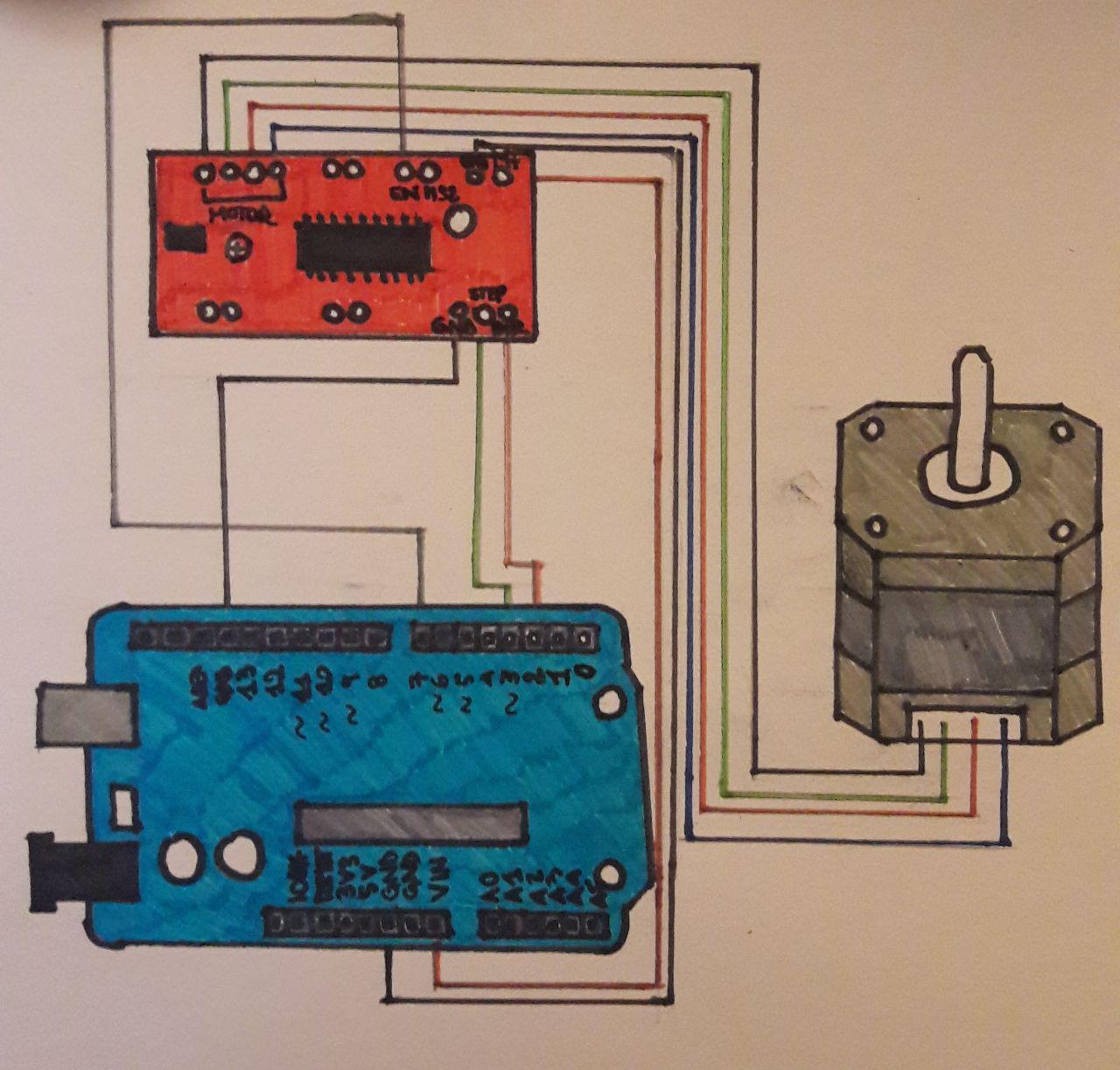
Photos of your hardware are not suitable for showing wiring connections - they are two easy to misunderstand. Just make a simple pencil drawing showing all the connections and post a photo of the drawing.
jremington:
A 9V battery is for a smoke alarm, not for anything related to Arduino, and certainly not for a motor. Post the current and voltage details of your "wall wart".
Stepping motors generally require separate power supplies providing 12 to 36 Volts at several Amperes.
I don't know a lot about the power requirements, so i read that a 9v battery was ok for 1 stepper, anyway i also tryed a different setup with the wall power adapter, these are the specs: AC 100V-240V DC 9V 1A
Robin2:
Please don't post pictures of text - just copy and paste the program and use the code button </>
You did not post a link to the datasheet for your motor.
Photos of your hardware are not suitable for showing wiring connections - they are two easy to misunderstand. Just make a simple pencil drawing showing all the connections and post a photo of the drawing.
...R
Ok, sorry again i edited the post once again. Hope everithing is clear now. Thank you for your suggestions
Your motor connections look terrible. If those loose wires ever separate or touch together while everything is powered, you will destroy the motor driver. It may already be destroyed.
Either solder the motor connections, or twist very well and tape/insulate them securely with electrical tape.
Note that the motor is 12V and your power supply is 9V. This will not work well, as about 2V is lost in the A3967 driver, and it probably won't work at all if the current limit on the motor driver is not set to maximum.
To what value did you set the current limit on the Easydriver?
jremington:
Your motor connections look terrible. If those loose wires ever separate or touch together while everything is powered, you will destroy the motor driver. It may already be destroyed.
Either solder the motor connections, or twist very well and tape/insulate them securely with electrical tape.
Note that the motor is 12V and your power supply is 9V. This will not work well, as about 2V is lost in the A3967 driver, and it probably won't work at all if the current limit on the motor driver is not set to maximum.
To what value did you set the current limit on the Easydriver?
I soldered the wires with few wire connectors after taking the photo so now they are ok.
The specs of the motor say 0.4 amps and 12v. That means that the minimum motor voltage must be 12v and 18v or 24v would be better. Just make sure not to exceed the max voltage of the Easydriver and also make sure to set the current limit on the Easydriver at 0.4 amps to protect the motor.
Have you studied the links I gave you in Reply #1?
Robin2:
The specs of the motor say 0.4 amps and 12v. That means that the minimum motor voltage must be 12v and 18v or 24v would be better. Just make sure not to exceed the max voltage of the Easydriver and also make sure to set the current limit on the Easydriver at 0.4 amps to protect the motor.
Have you studied the links I gave you in Reply #1?
...R
Thank you for your reply, so it could only be that it has not enough V to power it on? I can't find an arduino adapter higher than 12v and 2a, but i will continue searching, maybe i will. If i can't find something better do you think it could be enough?
This is from the easy driver technical data:
"From about 150mA/phase to about 750mA/phase
Supply 8V to 30V DC power input"
so there should be no problem even if i will use 24v, but the input voltage limit for the arduino board is 6-20v.
Yes, sure i have read the links you gave me, thank you, and were pretty helpful, but i am a beginner, so i still cannot understand a lot.
jremington:
Not true. It will work on less, but produce less torque.
Have you evidence of that? How much less?
It seems to me that if the OP is having a problem it is rather pointless experimenting outside the envelope. When he has the thing working that will be the time to see what happens with a lower voltage.