I am trying to run a NEMA 17 (17 HS4401) 1.7A stepper motor using A4988 driver. I am using a power adapter of 12V-5A output and powering the motor through the driver using a power supply module.
I have cross checked the circuit connections so many times. Also checked every wires and the motor if it is working. Checked the arduino using a simple LED light.
But when I try to run the motor, it doesn't run. When I upload the code, the arduino lights blink (which means the code is uploaded ig).
I can't figure out what is the problem.
I also measured the output voltage of the power supply, it's 9V.
what could possibly be wrong?
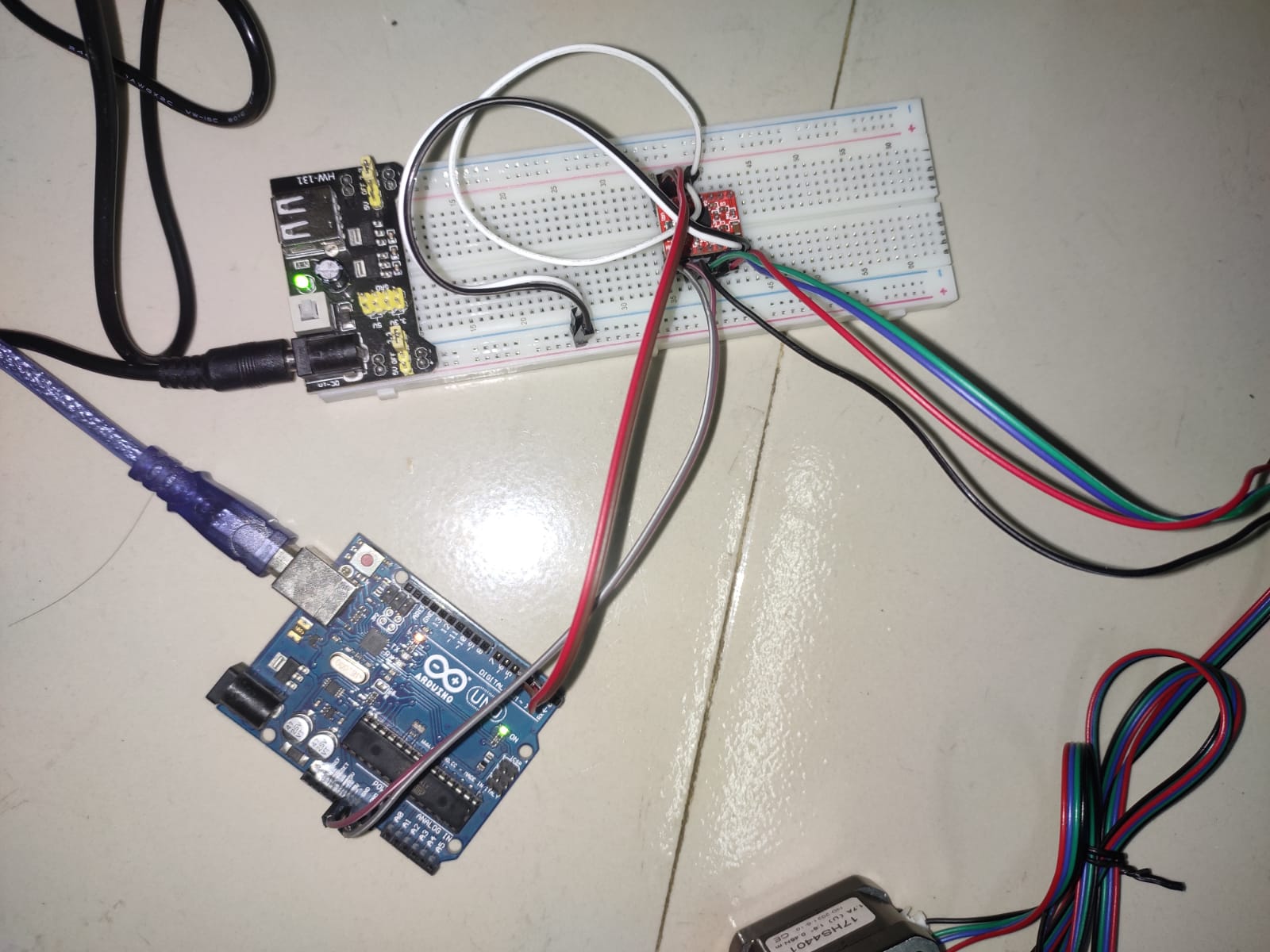
[ I have attached the link of the website that I followed for wiring and coding, and the pic of my circuit.] Followed website
Youtube? There's a lot of newbie stuff there. Even knowing people keep on showing 9 volt PP3 batteries as power source, ans this forum is shooting down the not running design.
You have the stepper supply connected to the protoboard through a regulator PCB, what is the voltage on the side bus rails that you are supplying power to the A4988 driver?
First of all, thank u all for taking the time to answer.
Yes, i have looked at it again. They didnt use the PCB. I Have seen their content on YouTube (they have a YouTube channel also). They didn’t show their power supply either.
The PCB i used was suggested by other videos.
Also, how would i connect the adapter to the driver directly? The connection port of the adapter is round.
This is the downside to these regulator boards. They don't give you easy access to the input voltage. I built an adapter using a male and female barrel and a 2 screw terminal to locate between the power adapter and regulator pcb. I can tie into the power adapter voltage at the terminal screws.
Thank u for your response.
I just measured the voltage, it's surprisingly 15V. But there was no deflection of the potentiometer at the output terminals.
Meanwhile i was measuring, i noticed a burning smell, and it was the ic of the PCB .
I think the problem was the PCB.
Now the pcb is gone.
Should i directly connect the 12V adapter to the driver? Is the driver capable of receiving 12V?
Or i should use any resistance?
Thank u for taking the time to respond.
I am nearly giving up rn.
I see no problem using the breadboard for a short period during proof of concept with an unloaded motor. The current may be as low as 0.5A without a load. Use the breadboard to see if you can control the motor. Just don't attach anything to the motor while it's turning.
Don't use the breadboard if you plan on putting the motor to work.
I've succeeded!
Thank u all for helping.
Though i Couldn't measure the voltage or current as i don't have the multimeter right now.
But it's working after-all!