Hi,
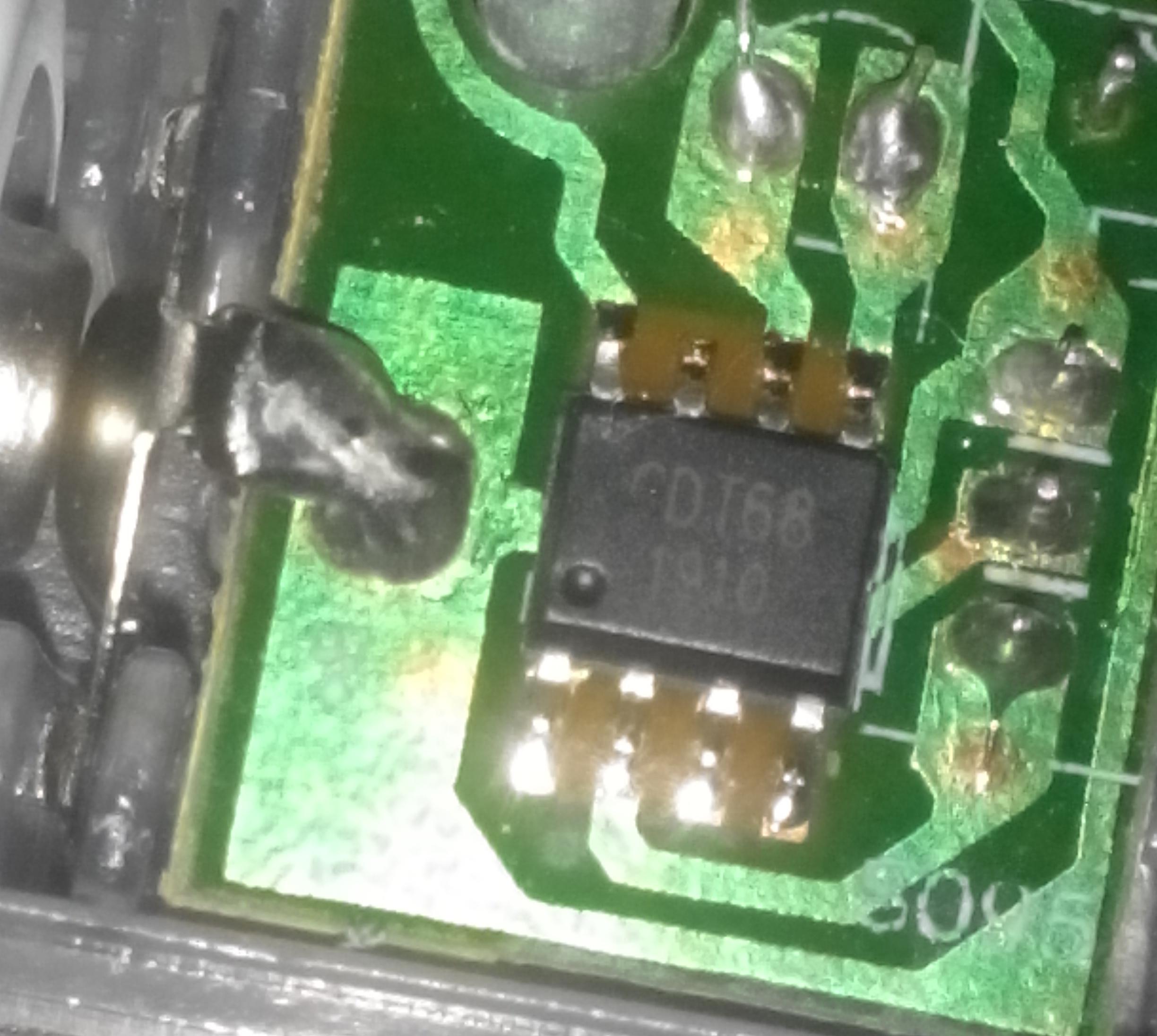
I have got a few cheap Christmas lights. The circuit is trivial - a SOP8 chip, a watch (?) crystal, a switch and 20 LEDs parallel. Powered from 2 AAs. I was surprised the chip is not the epoxy covered blob, and it even have markings: 1st row is GDT68 and the second one is 1910. I tried to Google but found nothing. I think it is a MCU. The pins of the chip are connected in this way:
GND
I/O (?) connected to the switch
I/O (?) connected to another pin of the switch
NC?
XTAL
XTAL
Vcc
LED cathode, it seems simple driver, no constant current something.
If it has a pin which can drive 20 LEDs in parallel, it may be a custom chip which might contain a small MCU core. MCU pins are not normally able to handle that much current. If so, it may not be reprogrammable, if that's where you're going with this question, and almost 100% certainly not using Arduino IDE.
(The first letter seems to be "C" but in direct sunlight it is clearly visible it is "G".)
The LEDs are some tiny SMD (I guess 0402) similar to this:
They all draw about 10mA and the voltage drop on the driver is about 0.4V - comparable to typical value of an AVR pin - another point for the MCU hypothesis.
I agree it is unlikely this chip may be programmed via Arduino IDE directly. But I think it is likely Arduino may be used to program this if I manage to find what chip it is and how to program it. Even OTP memory can be dealt with - you simply rewrite old code with NOPs and if enough memory is left...
I think the location of power pins and crystal oscillator is uncommon. I am quite sure no AVR has this configuration. I have hoped someone may remember seeing this.
EDIT: After posting this I had to leave ASAP and I did not have time to inline the pictures. It's fixed now.
EDIT2: For convenience I have traced the PCB connections. Yellow are connections to the (watch?) crystal which is in the common round THT package on the other side of the board. The board itself is single sided.
Thinking about the functionality required, one would expect the circuit to be some sort of LED driver. White LEDs would be pretty marginal on a 3V supply so it seems some voltage step up and current regulation would be in order. Are you certain that the other component is a crystal? I'd expect an external inductor or capacitor would be in order for a switch mode regulator.
If you have an oscilloscope, it would be interesting to see what's going on across the LEDs and on the "crystal".
It is a Chinese "toy" for slightly less the $1 (2 AA Alkaline cells included). No LED driver included. At 3V supply voltage the whole circuit consumes 13 mA from batteries. At 2.7V it consumes only 3.6 mA. At 2.5 V only 0.2 mA. Expected values for a while LED. If the circuit were a step up voltage converter supply current should increase with decreasing voltage. Also resistance of the crystal is very high - it cannot be a coil. There is picture of the other side of the board showing crystal:
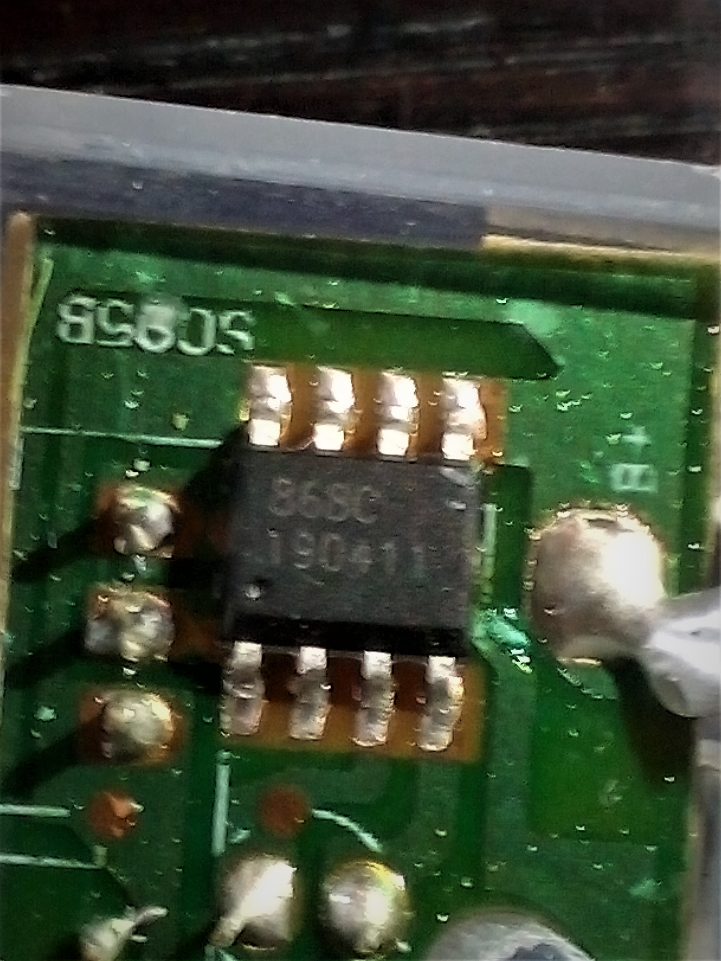
I have looked into other light. 4 of the have the same chip but the 5th has another one. The markings are 868C in the top row and 190411 in the bottom row. The other components and component placement is the same (but the chip is rotated by 180°) but it has a different pinout - the traces on the PCB are different. Functionality seems to be the same. Pinout of this chip is:
So what do they DO? Just On/Off? Blinking? "Breathing"?
China seems perfectly willing to produce dedicated ICs that perform functions like "combined blink and constant current regulator for blinking LED toys" that would embarrass western manufacturers. And then have a price/quality war on who can do it best for least.
I tend to believe that, although the particular model the OP has selected may not appear to do very much, the same design can be used to drive a much more sophisticated led array. He has probably got a model stripped of the remote control and selectable display profile.
Here, for example, is one which does a lot of tricks which imply the individual leds have some intelligence, yet the circuit boards, although obscured, appears equally small as the one in the OP. It also looks like a simple 2 wire daisy chain, implying a signal over the power wires.
That could explain the MCU and quartz crystal. The timing requirements for such a construction would probably be quite demanding (like e.g. WS2812) and an internal oscillator may not be good enough.
@6v6gt: You don't think cheap enough. In the more feature rich LEDs they are antiparallel so the controller is able to light one or the other set. Or both by quickly changing the voltage direction.
My LED string has three options - OFF; timer (6 hours ON and 18 hours OFF - probably the reason for the crystal) and continuously ON. Pulling the NC pin LOW also turns LED ON - I have no idea in what mode.
Further testing shown bad news for my hypothesis. The chip is in a deep sleep when no input is pulled low - current is < 1uA. When any pin is pulled LOW it turns on the LEDs in about 40 ns. It is too fast for a MCU to wake up, stabilize its clock and change output. It is probably an ASIC after all. Of course it can be a MCU with something asynchronous like CCL of the new AVRs. But it seems too expensive and complicated for such a cheap thing. Since there is no reason for such speed I think it is so fast because it is so simple - probably a counter gated by a simple logic circuit.
Still I find this interesting. From my (limited) experience cheap toys with ASIC include epoxy blob or unmarked chips. I expected that when it is in a standard package with markings it is some general purpose circuit. And since I don't know about newer logic chips with similar functionality I expected a MCU...
Well. I was trying to think "cheap" in terms of a basic platform shared between a range of applications with parts lopped out for the lower range models. If the chip and crystal is simply nothing more than an on/off switch and long term timer, that would be rather over-engineered, especially by Chinese standards. Surely the crystal would be the first thing to go.
The chain of leds intrigues me, however. Your statement about the 40nS startup time implies you have used an oscilloscope. Do you see any evidence of a signalling across the led chain to imply that the leds are something other than dumb lights ?
I could imagine that, even in a simple chain such as yours, the led may be individually switched in some way to preserver battery life etc.
@6v6gt: I have only a logic analyzer. I am almost sure the LEDs in this chain are naked. There is no waveform, simply ON-OFF action via a low side switch. I have another similar but mains powered and IR controlled LED chain. They are able to do "tricks". They are simply two interleaved sets of antiparallel LEDs as I said before. But because of China the frequency is low and they are flickering. It is nearly invisible at full intensity but well visible when dimmed.
I also spent a few minutes looking at Youtube videos of the fuller featured "Fairy" lights and it did appear to me that all of the patterns could be achieved by alternating the polarity of the leds on the chain (as you have pointed out), even the chasing flash which I originally thought must have required more intelligence in each led.
I am now wondering if the one you have, to achieve the steady on effect, uses such a chain but alternates the polarity quickly enough that you don't see it. That could at least explain why there is a chip there at all. Clearly, though, if the effects are created by simply altering the polarity of the applied power, then crystal accuracy is not required.
I dismantled it, tu use the chip and Batteryholder for a present.
I hooked up an osziloscope on the output, to find out, how the LEDs are controlled.
This chip use PWM with positive and negative polarity to control the two groups of LEDs.
The LEDs are alternately connected to the two wires on the output of the tiny board.
There is an 100ohm resistor direct behind the positive solderpad from the battery and a 240ohm resistor on one output of the chip.
If i would build something with a similar function, i would us a tiny45 or something similar. But i don't think this would match the price of the whole product.