Hope everything is going well, before I asl my question I must admit that I am Newbie and dont have any electronical backgroud, just working on a side project which is related with wearables.
Let me ask me question;
As you can see from the title, I have these 3 components but as far as I understood, I am unable to connect a Li-Po (Which is 3.7V and 250mAh) directly on to board. but I bought a module called TP4056 hoping it will help me.
My goal is to write the Gyroscope and Accelerometer data from the IMU sensors to the internal memory inside the card. Do you think I can achieve my goal with these 3 components?
Kind Regards and sorry for my insufficient knowledge background.
Does your li-po battery have a built-in over-discharge protection circuit? Many do, but maybe the smaller batteries don't, I'm not sure. If not, does your tp4056 module have over-discharge protection circuit? Some do and some don't. If you are not sure, post a link to the specs/product page of the battery and tp4056, or photos, and the forum can probably tell you.
Here is a really tiny li-po battery, only 80mAh, and you can see it's over-discharge protection circuit through the yellow tape. Hopefully your battery also has this.
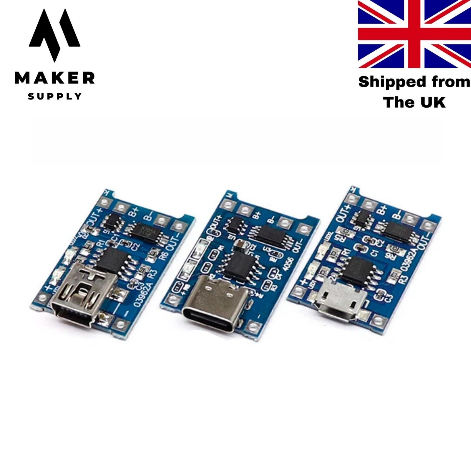
Here is the type of tp4056 module that does not have over-discharge protection. You can see only one 8-pin chip on the board. This type is suitable for charging and will protect the battery from over-charging, bit not from over-discharging.
I was about to say "surely that's wrong, the Nano 33 BLE is a 3.3V device". But then I checked the data sheet
Since VUSB feeds VIN via a Schottky diode and a DC-DC regulator specified minimum input voltage is 4.5V the minimum supply
voltage from USB has to be increased to a voltage in the range between 4.8V to 4.96V depending on the current being drawn.
That's very disappointing. A 3.3V device that can't run on a 3.7V battery without some boost converter which will make it less efficient.
I wonder if the Nano 33 BLE can be powered through it's 3V3 pin using an external regulator like mcp1700?
Product Description in English:
12V 1A DC DC Mini Voltage Amplifier Module is ultra-small in size and allows you to obtain the DC voltage you want. With this DC/DC converter, you can obtain voltage values between 5V - 12V.
Also I want to log Gyro and Accelerometer Data into internal memory card. But according to GPT writing data regularly into the card might harm its cell (Not sure). Also the size of internal storage is low for 2 hours long activities. In that case I want to add a external SD card reader and a Card.
To sum up, Adding given voltage amplifier model, a open/close switch and lastly adding a external sd card reader. Can I achieve all these goals with my nano?
I am aware that my questions are getting more and more boring, and if you answer, you will relieve me of a huge burden.