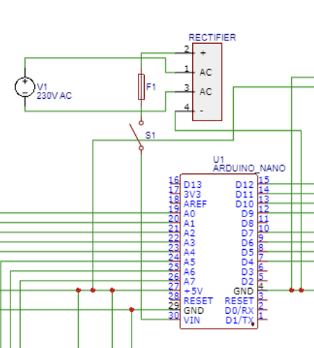
I am designing an Animatronic for my Uni project for graded unit 2. I've so far settled on using an Arduino Nano for the controller. This will then have a rectified 12V input, my question is, should I connect all four of my ULN20003 Motor Drivers directly into the Controller 5V out? I assume this shouldn't be an issue as they have current amplification though Darlington pairs built in. Thus current supply shouldn't be an issue for driving the 28BYJ - 48 stepper motors. Also since they are connected in parallel they will be receiving the 5V necessary to operate. -- But I've seen alot of posts saying there wont enough power output by doing this. I am unsure why and was wandering if anyone could help me understand this. Thank you in advance!
The logic part of the drivers, maybe. For the driver motor power: NO!
Please post a pen and paper wiring showing the connections and powering.
Powering controllers with 12 volt is always "on the limit" regarding using the 5 volt pin.
There is no Vcc on the ULN2003. That pin should be used for fly wheel diodes.
Your steppers must have their power coming from somewhere. This way is wrong as far as I can see.
Yeah I get this now, is it simply because there will be to much current drawn for the motors if they are connected this way?
In addition to what @Railroader says your 12V power supply won't work. If you just rectify 12VAC you get 100Hz (UK) pulsed DC with a peak voltage of about 17V. First you need a reservoir capacitor to smooth the DC then a voltage regulator of some kind. Ideally use a buck converter to get 5V and power everything with that. As @Railroader has said, you can't power motors from an Arduino. As another regular contributor often says: An Arduino is not a power supply.
Edit:
I just realised you are rectifying mains directly!!! Clearly I didn't read your schematic properly the first time.
The Arduino boards sends out control signals to drivers but they don't supply any motor power.
Your schematics is wrong!
The pin numbered 5 in the stepper datasheet is the power input, and that must come from an external power supply.
Yeah for the project itself i wont be touching anything close to mains. Ill use a DC power supply. Just theoretical for that stage, ive also designed a separate Rectifier with a transformer and bridge wave Rectifier into capacitor and voltage regulator. I wont be building this though, its mainly just to show my calculations make theoretical sense, I hope anyway. The symbol here was just a standard Rectifier, probably shouldve showed a transformer I guess.
A number of schematic packages do not show power pins for the part, although to correctly draw the diagram and as a preference, you should show a VCC and Gnd with decouplers for the IC's usually 10uF electrolytic and 100nF with a comment to place components close to the IC power pins.
ULN 2003 has internal freewheeling diodes.
Suggestion: Just write PSU instead of Rectifier on the drawing.
I think people will then understand its a hierarchical sub circuit.
"A number of schematics....". Who presented them? Don't buy everything found on the internet.
There are no power pins! The outputs connects to GND. Look into the datasheet! It shows what's inside of the circuit, NPN Darlington transistors.
Maybe they aren't actually ULN2003s, but instead driver boards with ULN2003s on them. E.g.:
A Nano's little UA78M05 voltage regulator probably can't effectively supply 100ma/coil to 8 coils, along with all the other demands it was sized for.
You need to find that out.
No, definatly not! Never use an Arduino board as a motor power supply. Period.
Please read the second sentence in reply #8 again. Then connect that to Your last picture. Does any bell ring?
Well that stops me buying Orcad then. ![]()
I was assuming the OP had called the COM Vcc , given the data sheet states "stepper motor driving applications requires a supply on the COM pin"
Yes. The tiny conductors on the board are way to tiny for motor currents, and there's no way such currents can come in to the board, neither by USB, nor from Vin.
You are showing pin 5 of the stepper going to a drive pin of the ULN2003.
These, 28BYJ-48 Stepper motors, are 5 pin unipolar stepper motors, where pin 5 goes to Vcc (COM on ULN2003)) and as Railroader has already stated should be a separate more substantial supply.
You could use the same PSU to operate the Arduino, but do decouple the lines close to the Arduino.
This topic was automatically closed 180 days after the last reply. New replies are no longer allowed.


