Hello, this is my first independent project. I'm a ME student and have some limited experience programming for arduino. But the hardware side is still pretty foreign to me.
What am I hoping to accomplish?
I want to use a microswitch as an input (trigger) for opening and closing a solenoid based on some variables controlled by the Nano.
This project shown on youtube is very close to what I hope to accomplish with a GUI and user-defined variables but the maker has disappeared from what I can find.
The first hurdle is the hardware.
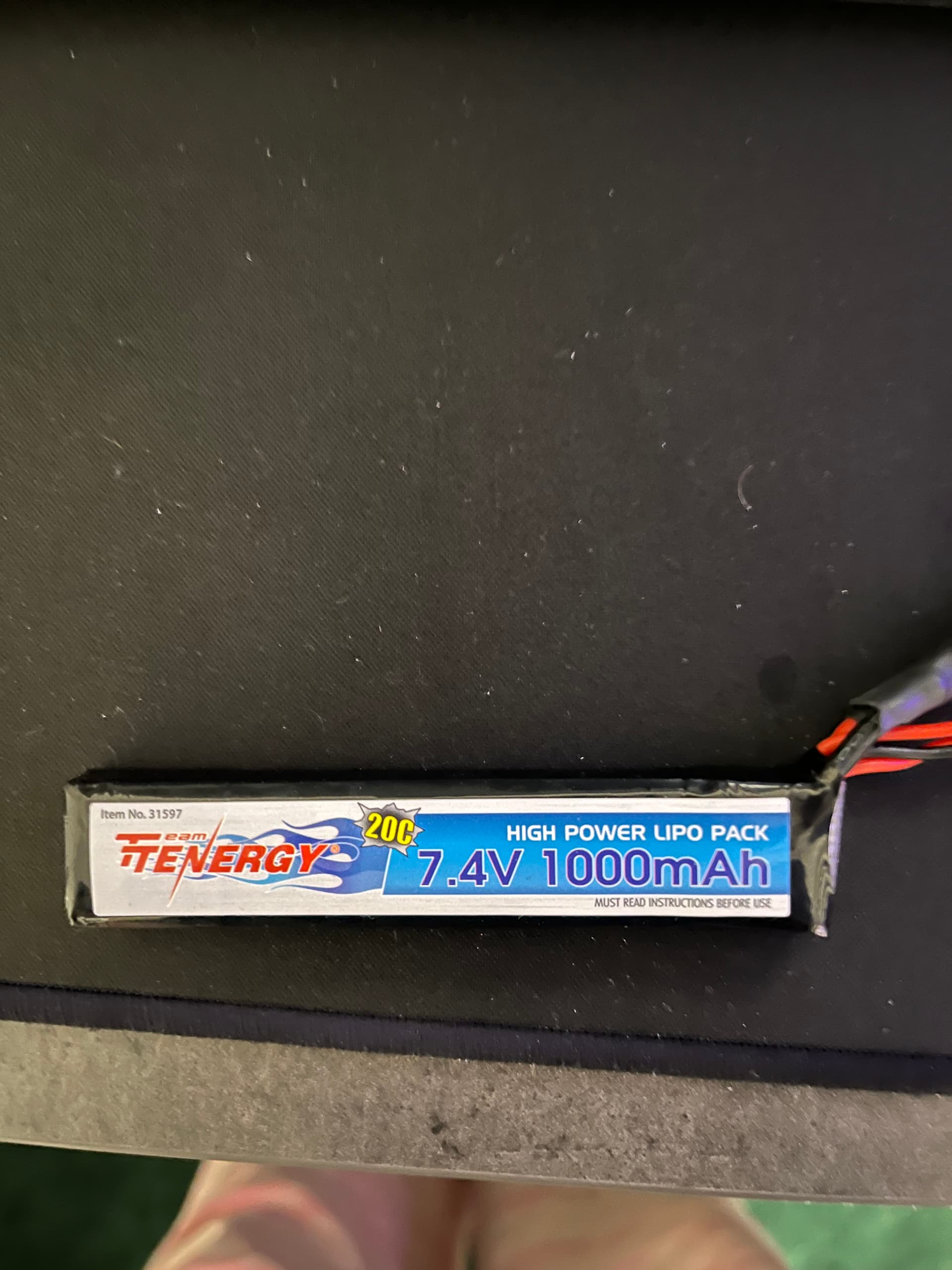
Battery is a 7.4v LiPo
Solenoid is a Mac bullet valve 5v 6w
I know the Nano can't power the solenoid directly, I'm looking for guidance on how to design a circuit that can signal the solenoid to open and close.
Eventually, I'll be connecting an OLED screen (as opposed to LCD in the original video) and a 5-way tactile switch for menu navigation. Fire mode will be controlled via 3 switches for a total of 5 modes to select from plus a safe mode (all off, 1st, 1st+2nd, 2nd, 2nd+3rd, 3rd).
I'm somewhat confident in the following schematic made in circuitmaker. This has the OLED, a microswitch, and the 5-way tactile switch. But I'm unsure how to connect battery and solenoid.
I know that the Nano pins can only output 40mA and if the 5v 6w solenoid is drawing 1.2A, that's not gonna fly. So I'm thinking I need a voltage regulator like this one https://www.pololu.com/product/2836 to take the battery voltage down to 5v and then provide the current that I need. I also have been reading that I need to do something about the back EMF created when the coil discharges, so some kind of diode? But how to connect it all? That's where I'm lost. If I can just get past the hardware side, the programming is relatively easy for me.
I have not, I'm nervous about cooking something because I don't understand something properly. I guess the first thing is how should I go about selecting a microswitch? What characteristics do I need to look at and how do I go about selecting the right resistor for it?
You select a microswitch to fit your design. There are hundreds of physical shapes and ways to make the switch operate. Almost all are spdt, single pole Double throw.
Why a resistor?None needed or should be involved. One wire from the switch to that Arduino ground, the other wire to the Arduino digital pin. The pin being set to input PULLUP! Then your code will watch for the digital pin to go LOW, indicating the switch was pressed.
I was under the impression that when connecting switches it was best practice to have a pull-down resistor in place. In the videos I've watched on the subject, they used a 10kohm resistor but I'm not sure why that value was picked. But supposedly it enables a small amount of voltage to get to the input pin in the LOW state to eliminate any floating. Is that not correct?
Yes, that is correct, if you want to, but much easier to use inputPullup() and let the internal resistor do it for you and connect the other side of the switch to ground. The logic is inverted so the normal setting of the pin is HIGH. when pressed the pin goes low, but a minor difference in programming.
Okay, I did not know that there was an internal resistor like that. Perhaps the tutorials I was watching were trying to cater to more general purpose as opposed to just Arduino. If that is the case, would the same apply to 5-way blade switch intended for the fire selector, and the 5-way tactile navigation switch? As in, no resistors needed for any of the inputs?
Does inverting the signal like this have any noticeable effect on battery life?