A0 is connected to the SPI chip select of a MAX3100 IC. There shouldn't be any way for damage to occur this way. I have the exact same set up for digital pins 2-11 without any issue. A1-A3 are not connected to anything, but also show the same behavior as A0.
The only way i could think to have damage is handling/static.
I don't think the Analogue pins work like you think they should. An analog write is known as a PWM on this processor. And analog write never worked on analogue pins on any Arduino I know of.
AnalogWrite() is one of the functions mentioned in the arduino documentation for RP2040 and for most arduinos, however I am actually more interested in using a digital write (which also should work with analog pins provided you set them up correctly). I simply want to use A0 as a CS pin for SPI comms. I have not seen anyone mention this as an issue before, so i begin to assume it is a hardware issue on my end.
Looking at it with a scope does not show any sort of PWM signal.
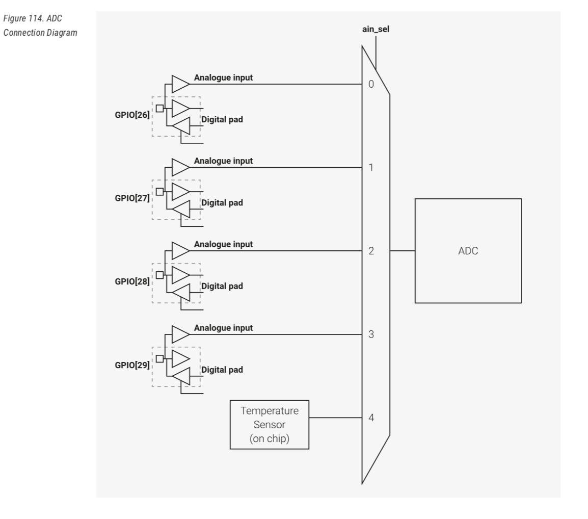
It quite clearly shows that there are only four external pins and one internal pin into the ADC's multiplexer.
However the "extra" analogue input pins do go into the NINA-W102-00B Wi-Fi chip as it has a some pins that can be used as an A/D. So the claims in the data sheet are strictly correct.
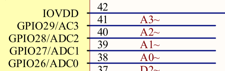
If you want to use the analogue pins as an output, it is probably worth trying to use the alternate GPIO pins instead of referring to the analogue pin. This is taken from the Connect schematic.