I'm working on a DIY AC mains power monitoring system using Arduino. My setup includes two power supplies: AC mains Lead-acid operated sine wave inverter (powers the home during mains failure).
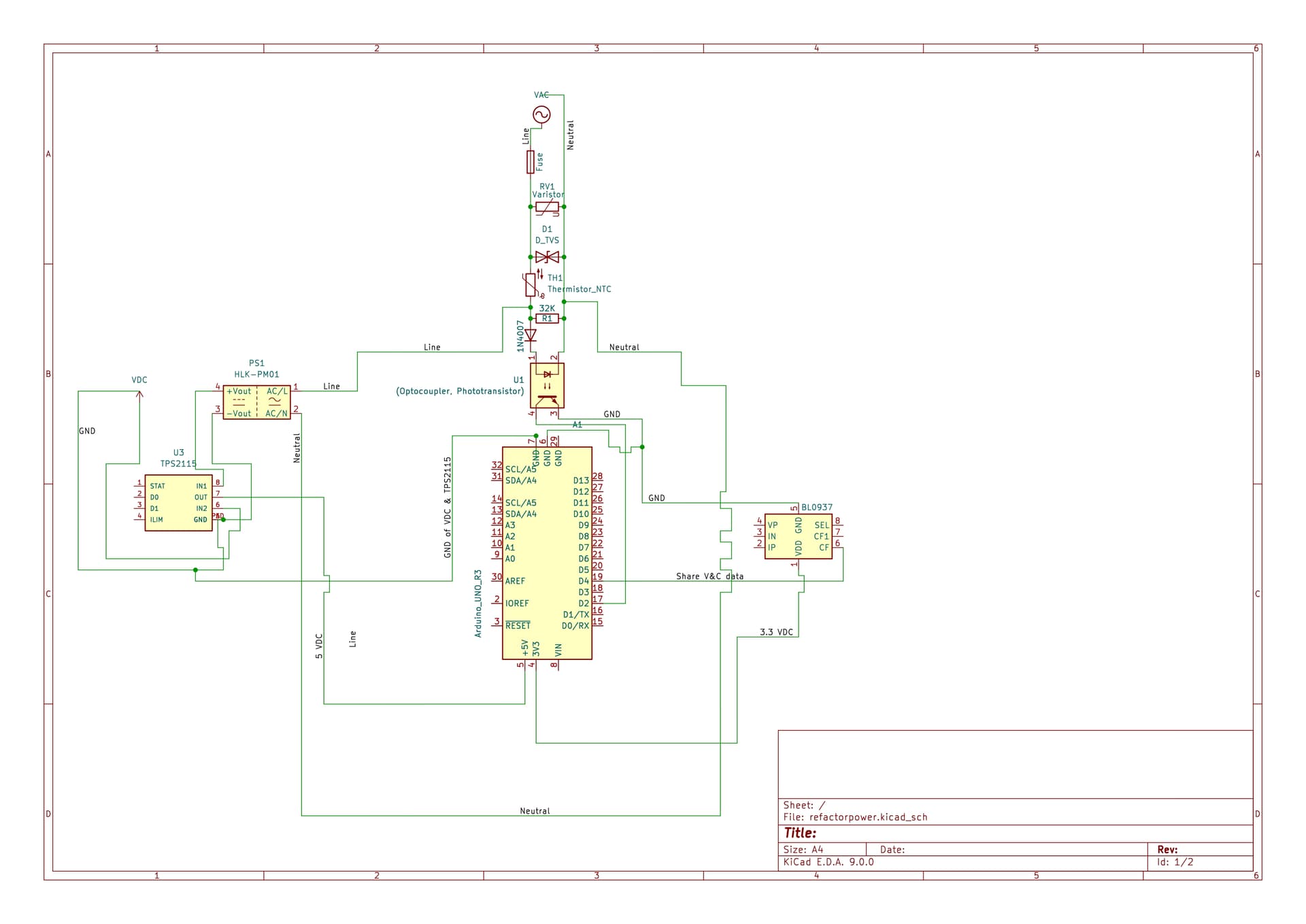
For AC mains failure detection, I'm using an opto-coupler. The protection chain before the opto-coupler includes:
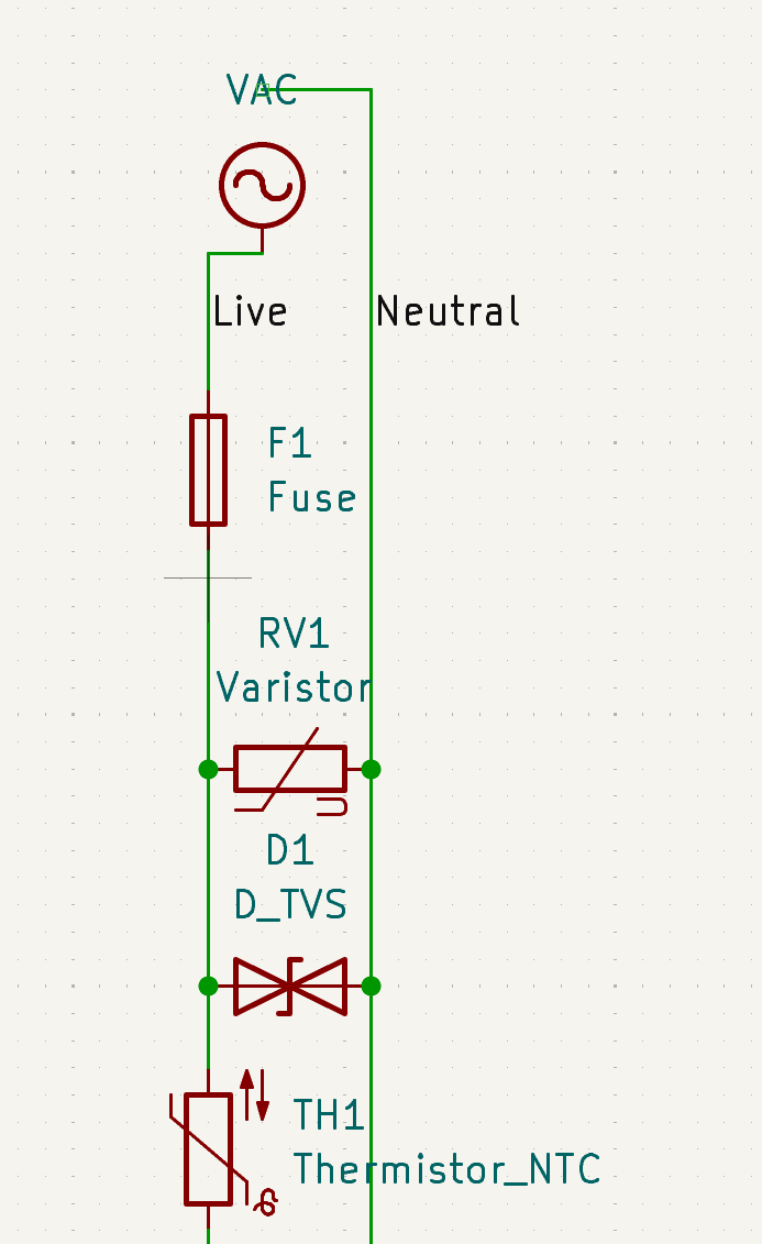
Fuse
MOV (Metal Oxide Varistor)
TVS Diode
NTC Thermistor
The AC mains input comes from an outlet without back power (i.e., not connected to the inverter).
To power the Arduino:
HLK-PM01 module for converting AC (post-protection circuit) to DC.
A second DC source from an AC to DC adapter powered by the inverter.
TPS2115 for seamless switching between power sources during failures.
This is my first schematic, so please excuse any mistakes. How can I improve this design? Am I missing any key protections or components?
Your feedback is highly appreciated!
NOTE: To be honest, it was getting late, and I wanted to post it quickly. I knew I should have refined the schematic to avoid any ambiguity, but I gave in to the temptation to share it as-is.
Also, I wasn’t entirely sure how to properly represent Live and Neutral connections from VAC and VDC sources, so I just drew two wires from the VAC and VDC symbols.
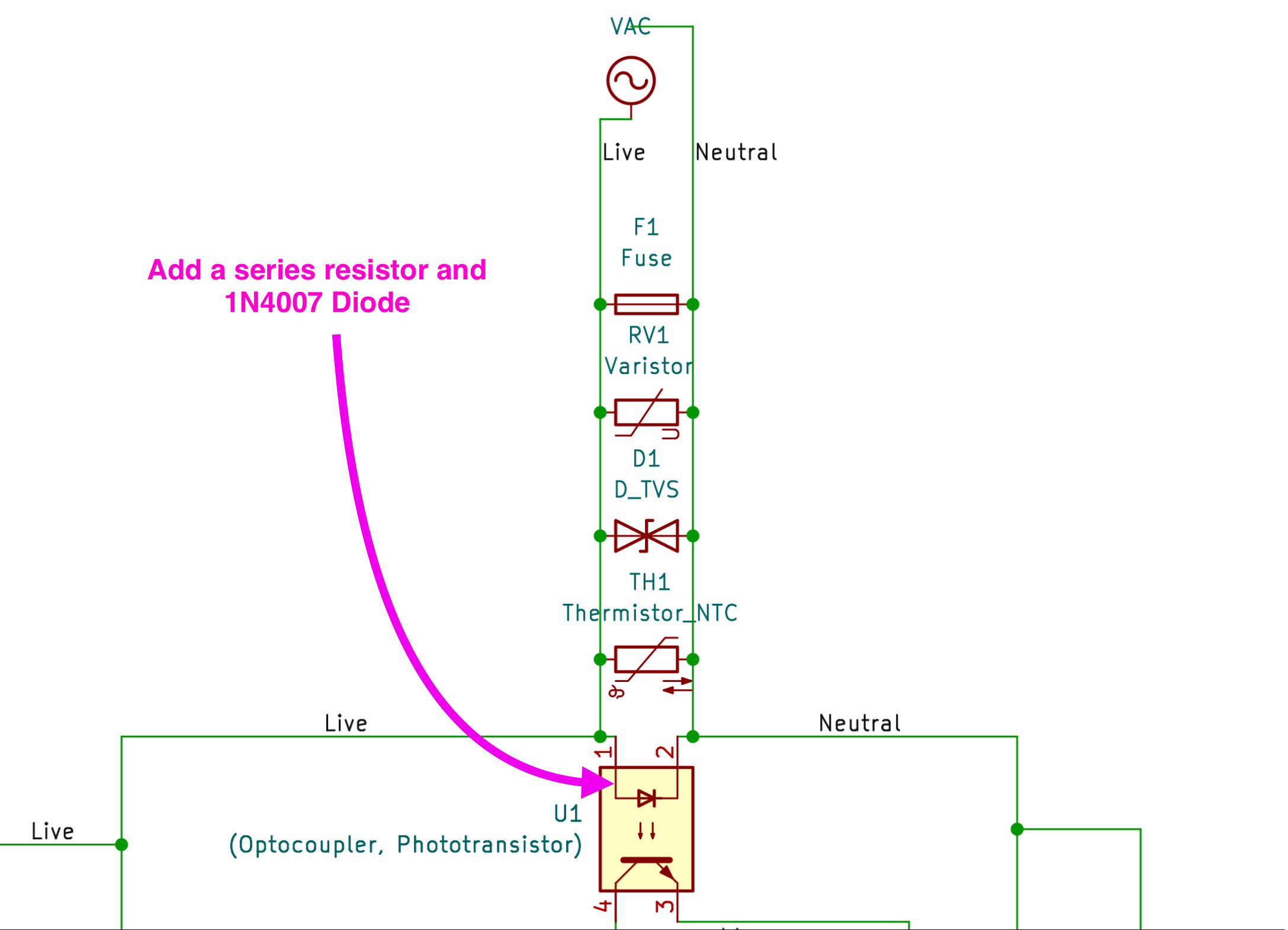
UPDATED SCHEMATIC DIAGRAM (UPDATE 1)
I have corrected many mistakes and errors in the updated schematic diagram. The work on connecting the BL0937 to the Arduino is still pending.
This bit of the circuit will probably pop the circuit breaker in the house, as well as vaporize the optocoupler input, along with significant parts of a PCB. It appears to be a short circuit directly across the line.
You should learn more about circuit theory before even thinking about line powered projects. Or at least use a safety certified wall wart power supply.
I don't want to appear rude and unhelpful, but I would strongly suggest getting some basic electronic knowledge before tackling this type of project. It's not just a style thing ,it's an avoid doing something quite dangerous thing.
However, willingness to learn and asking for advice are good steps.
I hesitate to nitpick style issues after the error noted by @jremington , but there are conventions really worth following like having grounds at the bottom of the page, and power sources towards the top of page. You seem to have a mix of net labels and wires. I would stick to the former.
Thank you, @jremington, for pointing this out. This is my first time using software to create a schematic, and I truly apologize for any mistakes or misunderstandings on my part.
Is the main issue because I didn’t include a current-limiting resistor for the optocoupler? What else do you think I might be missing?
To be honest, it was getting late, and I wanted to post it quickly. I knew I should have refined the schematic to avoid any ambiguity, but I gave in to the temptation to share it as-is.
Also, I wasn’t entirely sure how to properly represent Live and Neutral connections from VAC and VDC sources, so I just drew two wires from the VAC and VDC symbols.
Thank you, @bobcousins, for your valuable feedback. I truly appreciate the time you took to review my schematic.
Not at all! I genuinely welcome constructive criticism. It’s essential for my learning and improving this project.
I completely agree. I realize I rushed this one. It was late, and I couldn’t resist posting it even though I knew I should refine the schematic further to avoid ambiguity. I’ll definitely take a step back to build a stronger foundational understanding before proceeding.
Thank you for pointing this out. I will follow these conventions in future revisions.
I’ll look into this further, as all schematics tend to have many wires running through them. Understanding this will help make the schematics clearer, clutter-free, and free from unnecessary ambiguity.
I wasn’t entirely sure how to properly represent Live and Neutral connections from VAC and VDC sources, so I just drew two wires from the VAC and VDC symbols.
There are so many serious problems with the posted schematic that it is not worth further discussion.
However, it does reveal how little useful understanding you have of basic circuit principles.
At this early stage, I recommend that you not undertake any project connected to an AC line, as the attempt could be fatal. Stick with battery powered projects and you will learn.
Thank you for your honest feedback. I completely understand your concerns and take them seriously.
I totally get your point and will definitely start with battery-powered projects to build a solid understanding before attempting anything related to AC lines.
However, I would greatly appreciate it if you could point out the specific mistakes I made in the schematic. The main reason I posted this was to identify my errors and learn from them. Your insights would be incredibly helpful in guiding me in the right direction.
Thanks again for taking the time to review my work.
Thank you, @TomGeorge, for the suggestion. This is quite interesting, as it would eliminate most of the components from the circuit.
From what I understand, I’ll need to use two power sources (wall wart power supplies):
1 One connected to the outlet without the battery-operated sine wave inverter.
2 The other connected to the inverter-powered outlet, ensuring the second power supply remains active during an AC mains outage.
Additionally, I’ll need to use a power switch IC like the TPS2115 to switch between the two power sources seamlessly.
What do you think about this approach? Also, to detect an AC mains power outage, we will need to retrieve power switching data from the TPS2115 (if possible)?
Hi, @lifelonglearner24
Why power your project of the inverter?
You have a battery bank.
Continuousy power your project off the battery bank with a DC-DC converter.
That way your controller is permanently on an uninteruptable supply, unless the battery bank goes flat, in which case you will have no backup mains either.
Monitor your battery bank as well with your project.