I would like to make a bright light, with 5-10 3W RGBLEDS connected in series (these ones).
I have a 24V 1.5A AC adapter that plugs into the wall, to give me a constant current and voltage...
I'm thinking of how I could make this work, and I'm a real newbie to doing anything outside of just connecting things straight to the arduino and connecting the arduio to my PC, so I'm really not sure of some things, and I don't know if this will work. I'm thinking that maybe, I could connect the arduino in parallel with something like the L7805CV to drop the voltage from 24V to 5V, and have the arduino control 3 variable resistors hooked up to the other branch of the circuit, that feed into the each RGBLED pin. That way I could vary the voltage as needed to alter the colors. I am planning on connecting multiple of these RGBLEDS in series so that I'm not pumping 24V straight into the pins... But I have some areas where I'm confused.
I see online that the different pins for R,G and B require different resistors on account of the differing forward voltages of the different colors. Could I just account for that in my variable resistors and not bother with the resistors in front of the LEDS?
Very similar to my first question, but still something I need specific clarification on: Do I need to have a resistor like this before each RGBLED, or can I just use the variable resistor at the start?
I see that these LEDS require a driver. I don't know how to use one, but I can find out.. Unless I don't need one because of my constant 24V current adapter. Is this the case, or do I still need a driver? If so, which one would suit my purposes?
Is there anything I haven't considered that would derail this whole project?
As far as the programming goes, I am a programmer and can manage. I really just need help with the physical setup.
You can't connect RGB LEDs in series because there is a common anode or cathode shared by the 3 internal LEDs.
Although it's possible to use a current-limiting resistor with "high power" LEDs (like with a regular little LED). It's not a good solution and it's rarely done. If you want to do that, make sure to calculate the power dissipated by the resistor (Voltage squared/Resistance is one way to calculate power). A little 1/4W resistor will burn-up. And in this case, you'll need one resistor per-LED per-color (9 resistors).
Normally, high-power LEDS are driven from a constant current (or controlled-current) switchmode driver. That's NOT an easy thing to build yourself.
You can use a potentiometer on an Arduino input to control the brightness with PWM (assuming the LED driver is PWM controllable) but the power requirements prevent you from putting a pot or variable resistor in series with the LED.
LEDs greater than 1W also normally require a heatsink.
Well it won't derail your project, but the LEDs in the link have a white chip in them, too.
RGBW.
Is your power supply constant current or constant (regulated) voltage or neither? Not both!
Share a link to it, or at least a picture.
Usually dimming is done with PWM supplied by your code.
Typically you would have a number of red LEDs in series and one resistor to adjust the current, and a low-side mosfet switch to do the PWM. Repeat for each color including white.
You'll work backwards from the maximum current available to select the series resistor in each color stack.
It looks like for 10 LEDs you could do two stacks for each color and use just one transistor switch per color.
@DVDdoug take the OP's link, these look like unconnected LEDs. But +1 on everything you said.
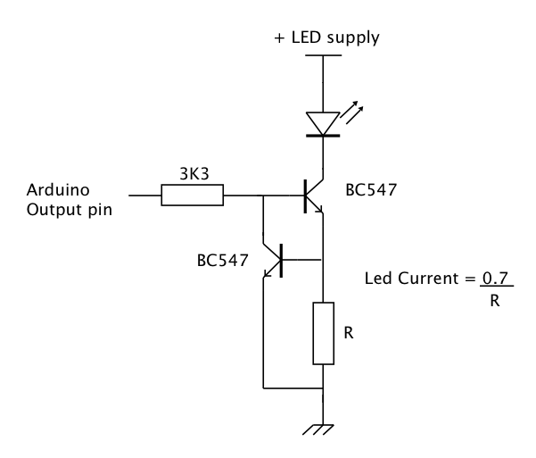
"0.7" or "0.5" relates to the VBE base-emitter threshold of the lower transistor. 0.7 probably is a little high.
Vfs?
If you are asking how much minimum voltage drop this circuit requires, then it is slightly more than two VBE drops to keep the transistor in this case, not saturating.
Since it is not saturating, you can use the actual β of the upper transistor to determine the resistor value. But you have to use the β for that particular collector current.
Typically you would have a number of red LEDs in series and one resistor to adjust the current, and a low-side mosfet switch to do the PWM. Repeat for each color including white.
So I finally learned about how transistors work and this is exactly what I was looking for xD
Although I don't quite understand what you mean when you say that for 10 LEDs I could do 2 stacks for each color. What do you mean by stacks? Do you mean 2 separate series connections of 5 leds each?
So I did a quick diagram to show you what I understand by what you said about the mosfets.. I know that I used symbols for bjt transistors and not mosfets, but I don't understand what's happening with the different mosfet symbols, but am busy youtubing all that now. The circuit will get completed obviously, I just did a quick illustration of the series connections and the low end transistor setup. Is this in the ballpark of being correct? I see in other comments there is talk of a different setup, that looks simpler. I don't have time to also reply there at this moment, but I want to take a second to figure out what's happening in the diagram anyway.
The power supply is constant voltage and should deliver 1.5 A at 24 volts (36 watts), the circuits will draw whatever current they do.
Test the power supply to see if it meets its specifications. A full torture test would be 16 ohms capable of handling 36 watts - I make these out of smaller power resistors, like 4 4 ohm 10 watt power resistors in series. They will get hot.
An alternate would be two 12 volt lamps in series. I use bulbs from the auto parts store.
Or don't test until you are really doing the LEDs. You would not be the first, I only mention testing because a certain percentage of questions here come down to power supply issues.
You could leave a bit of spare capacity or get a bigger power supply. I will leave that point to someone else, I just conservative, so.
Yes, all well within the ball park, a few details around the mosfet circuit you don't show but are well known and simple.
And yes, by two stacks I did mean that each channel mosfet switch could drive two [series connected resistor + LEDs] wired in parallel.
But I do like the alternate constant current suggestion. I just never did that in this circumstance - I deal with low current LEDs, misfits mosfets work fine.
So leave the constant current idea on the table. It's a few more parts, perhaps someone will advocate intelligently for using that design.
Okay I'm back, sorry for disappearing, I was off learning this stuff and working my job xD
So I'm wondering about the thing you said about some common well known issue with the transistor setup I had proposed. Could I get some clarity on that?
Also, I don't know how to figure out which mosfet to use, but I thought about it and... is this a good one to use...?