I'm building a board with 3 RGB LEDs and a bit confused about wiring it.
Each RGB Spec is:
R: Vf=2V, 20mA
G and B: Vf=3.1V, 15mA
Anode is common.
Basically I have two questions
Will it work if I connect them as shown on this schematic? I believe my VCC needs to be more than 9.3V because G and B have forward voltage 3.1V. So I'm going to use 12V as supply voltage.
Am I correct assuming that I can get away with small SMD BJT NPN transistor (something like MMBT3904LT1G) because current going thru each will not be above 100mA?
The above drawing may shorten the life of two LEDs if the third fails, as the current will be shifted from three LEDs onto the two remaining 'good' LEDs.
I'd use separate resistors for each LED -or- strings in series, three of each colour if +Vled is high enough.
Use a calculator to determine the correct series resistance in either case - based on your +Vled (less 0.6v drop for the transistor)
(I wouldn't call it +Vcc, as it may get confused with +Vcc used on the micro etc, with the associated smoke and tears! Letters are cheap!
You should not do that. The Vf might vary per e.g. red led.
Below from the datasheet of a white led (the principle is the same for each colour in your RGB leds)
Parameter       | Symbol | Condition | min | typical | max | units
----------------+--------+-----------+-----+---------+-----+------
Forward Voltage | Vf     | If = 20mA | 3.0 | ----    | 3.6 | V
So the one led can have a forward voltage of 3V and the other one of 3.6 V.
As a result, the setup will attempt to have different voltages at the point where all leds connect to the resistor which is not possible. And hence something has to give in.
You're counting voltage drop to consider a 12V source when you have things wired in parallel.
Big whoops. Maybe refresh yourself on what the difference between series and parallel is.
And then maybe during your learnin efforts, you'll understand why parallel LEDs are not a good idea as some have hinted at so far.
Will it work if I connect them as shown on this schematic? I believe my VCC needs to be more than 9.3V because G and B have forward voltage 3.1V. So I'm going to use 12V as supply voltage.
So the LED forward voltage is 3.1V being supplied by 12V.
That puts 12-3.1V = 8.9V across a 330R resistor.
Which means the current through the resistor and hence through the LEDs is 8.9 / 330 = 27mA
This is more than the standard 20mA maximum for an LED. Plus the problems of current sharing (they will not share evenly ) of parallel LEDs.
I believe my VCC needs to be more than 9.3V because G and B have forward voltage 3.1V.
Many people believe things that are not true. Looks like you are one of them. Forward voltage drops only add up when they are in series not in parallel.
lastchancename:
The above drawing may shorten the life of two LEDs if the third fails, as the current will be shifted from three LEDs onto the two remaining 'good' LEDs.
I'd use separate resistors for each LED -or- strings in series, three of each colour if +Vled is high enough.
Use a calculator to determine the correct series resistance in either case - based on your +Vled (less 0.6v drop for the transistor)
(I wouldn't call it +Vcc, as it may get confused with +Vcc used on the micro etc, with the associated smoke and tears! Letters are cheap!
Thanks! Yeah I was calculating as if they were in series, while actually making diagram for parallel connection. Don't ask me why, lol I glad you guys pointed that out!
I don't see any way to connect them in series since they have common anode, so looks like I will need resistor for each LED. In this case I don't see why I can't power whole thing with 5V supply, or am I saying nonsense again?
Dose this make more sense?
If I understand it correctly, in series current is same across all LEDs and voltage is added. In parallel, voltage drop is the same but current is added.
So not counting other components, total current consumed would be under 100mA, and at each transistor a little over 30mA? And total voltage drop would be 3.6V?
Oh and thanks for the voltage drop against transistor, I didn't think of that
Are you intending to turn on all 3 in a group at once, which will result in some shade of white, with overall white brightness determined by having 1, 2, or 3 groups turned on/PWMed?
Or did you intend to have all Reds on one transistor, Blues on 2nd, and Green on a third so you could also mix colors?
CrossRoads:
Are you intending to turn on all 3 in a group at once, which will result in some shade of white, with overall white brightness determined by having 1, 2, or 3 groups turned on/PWMed?
Or did you intend to have all Reds on one transistor, Blues on 2nd, and Green on a third so you could also mix colors?
Thank you CrossRoads!!!! A big woops on my end!
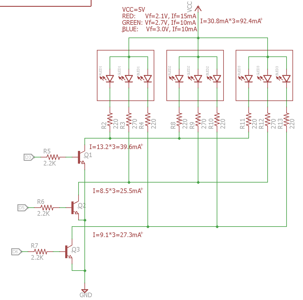
Yeah I want to control each color with transistor. All REDs with one, all GREENs with another and all Blues with third one... This is basically for small edge lit sign...
You right the way I have it now I can only do white light (not even pure white).
I think this should be correct:
Looks good to me. I'd make R5, R6, R7 smaller so Q1, Q2, Q3 go fully into saturation when driven and their Vce is minimized. If you figure Vbe will be ~ 0.7V (one diode drop equivalent) and the Arduino output is 5V/20mA, then
(5V - 0.7V)/.020A =215 Ohm, so 220 or 270 would be better.
Then even if the Arduino drops to 4.2V you still have plenty of current drive to turn the transistor on.
CrossRoads:
Looks good to me. I'd make R5, R6, R7 smaller so Q1, Q2, Q3 go fully into saturation when driven and their Vce is minimized. If you figure Vbe will be ~ 0.7V (one diode drop equivalent) and the Arduino output is 5V/20mA, then
(5V - 0.7V)/.020A =215 Ohm, so 220 or 270 would be better.
Then even if the Arduino drops to 4.2V you still have plenty of current drive to turn the transistor on.
Thanks!
I was planning to power my ATmega328p with 3.3V via voltage regulator... Would it still be able to drive transistors (MMBT3904LT1G) ?
(3.3V-0.7)/.020A=130 Ohm right?
Once I started looking at which RGB chips to order from mouser I realized that WS2812B LEDs cost same or less, and don't even require current limiting resistor or transistor since they have IC on-board!
Just need a decoupling capacitor fore each and resistor for data line. Wow this makes this project so much easier!
In fact I think I can design PCB that will have a foot print for several LEDs, but can only install one or two or more when needed. So much more flexibility!
I can probably even drive whole thing with ATtiny micro, although not sure if it can handle IR and BT processing...