I'm connecting an Arduino UNO, with a 20X4 LCD, and a 4X3 keypad, want to get the input number from the keypad and display on the LCD.
Please see the code in below:
///////////////////----------LCD Connection------------////////////////
/*
The circuit:
LCD VDD pin to +5V
LCD V0 pin to GND
LCD RS pin to digital pin 12
LCD R/W pin to digital pin 11
LCD Enable pin to digital pin 10
LCD D4 pin to digital pin 5
LCD D5 pin to digital pin 4
LCD D6 pin to digital pin 3
LCD D7 pin to digital pin 2
LCD +LED pin to digital pin 13
LCD -LED pin to GND
*/
////////////////////////////////////////////////////////////////////////////////////////////////////////////////
///////////////////----------Keypad Connection------------////////////////
/*
The circuit:
Keypad pin 1 – digital pin 12
Keypad pin 2 – digital pin 11
Keypad pin  3– digital pin 10
Keypad pin  4– digital pin 9
Keypad pin  5– digital pin 8
Keypad pin  6– digital pin 7
Keypad pin  7– digital pin 6
*/
////////////////////////////////////////////////////////////////////////////////////////////////////////////////

#include <Keypad.h>
#include <LiquidCrystal.h>


///////////////////----------Read and Store Date------////////////////////
char rsdata;
/////////////////////////////////////////////////////////////////////////////////////////

///////////////////----------Keypad Setting-------------////////////////////
const byte ROWS=4; //4 rows
const byte COLS=3; //3 columns
char key[ROWS][COLS]={

  {'1','2','3'},
  {'4','5','6'},
  {'7','8','9'},
  {'*','0','#'},
};

byte rowPins[ROWS]={11,6,7,9};
byte colPins[COLS]={10,12,8};

Keypad customKeypad=Keypad(makeKeymap(key) ,rowPins, colPins, ROWS, COLS);

//////////////////------------LCD Setting--------------------//////////////
int backLight = 13;    // pin 13 will control the backlight

// setup LiquidCrystal lcd variable
//                 LCD pin:  rs, r/w, enable, d4, d5, d6, d7
//              Arduino pin:12, 11,        10,   5,   4,   3,  2
LiquidCrystal lcd(12, 11, 10, 5, 4, 3, 2);

////////////////////////////////////////////////////////////////////////////


void setup() {

Serial.begin(9600);

pinMode(backLight, OUTPUT);
digitalWrite(backLight, HIGH); // turn backlight on. Replace 'HIGH' with 'LOW' to turn it off.
 lcd.begin(20, 4);     // setting of LCD (4 x 20)

 // Try to print somethings on LCD (IT IS WORK FOR THIS PART)//
  lcd.print("Printing text");
  delay(2500);
  lcd.clear();
  lcd.print("Enter a Number");
delay(1500);
}


///////////////------void loop------////////////////////////////

void loop(){
lcd.clear();
lcd.setCursor(0, 1);
lcd.print("HI"); // ( I can print this "HI" on LCD)
char customKey = customKeypad.getKey();
  if (customKey!= NO_KEY){
    Serial.println(customKey);
    lcd.clear();
    lcd.setCursor(0,2);
    lcd.print("GOT KEY");
    delay(2000);
  }

}
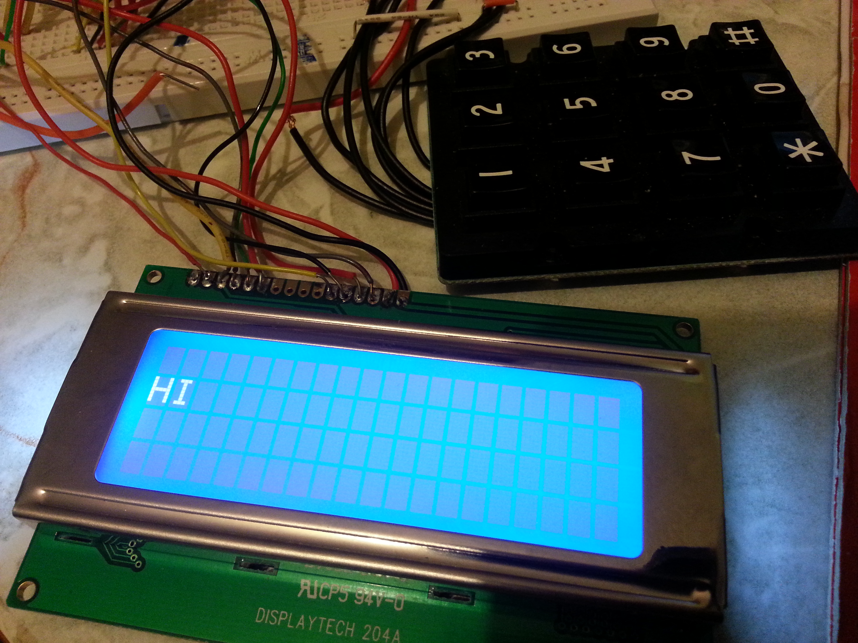
Result:
I can print "Printing text" and "Enter a Number"
and the LCD is cleared
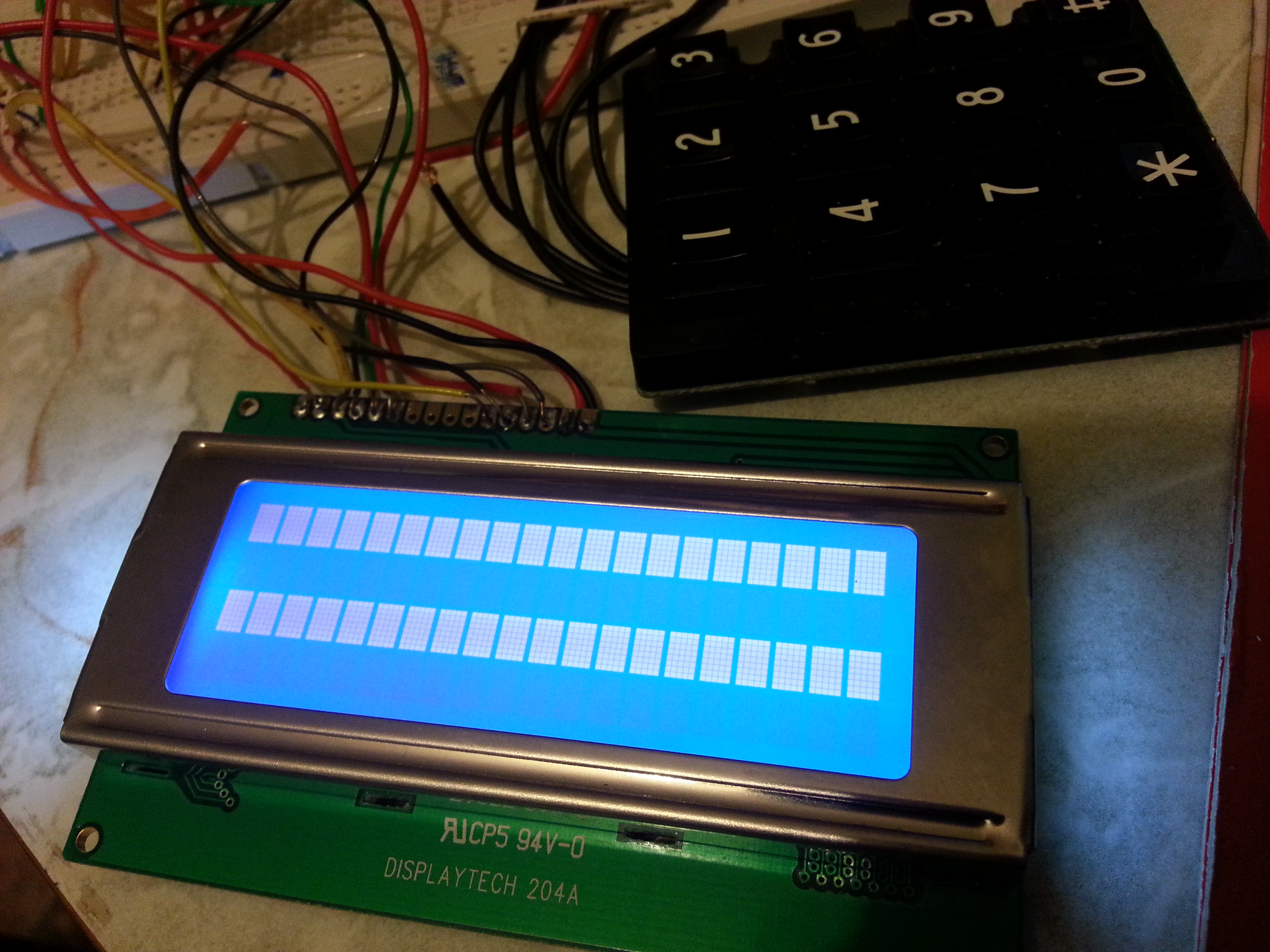
Then “HI” is print on the LCD
Now, I press a number “8” from keypad:
On Serial Monitor: 8 is showed
On LCD: The text” HI” is gone, but “8” did not show on the LCD