I am making a scoreboard with LED strip lights. They use 12v, so I got a bunch of transistors to carry the load. But I don't think I am wiring it correctly with the shift register. Here's what I have so far.
One, I think I need some resistors maybe? The LEDs just use 12v, so I don't think I need any resistors in series with them. But what about on the base of the transistors? Right now I am using PNPs, but I do have NPNs if I need to switch to them. Also, I have my scoreboard constructed, and I have all of the negative leads of the lights tied together, so whatever I change, I need to keep the lights with the common negative tied to ground.
MrGibbage:
One, I think I need some resistors maybe?
Look and see whether the strips have them built in. There are problems with your transistor circuit. You chose a common collector configuration, which works differently than the usual common emitter circuit. It will only supply about 4.2 volts to the LEDs and might overload the Arduino pins.
Those transistors are PNP darlingtons so need the collectors to have negative voltage with respect to the emitters. You have them the wrong way round. You do need resistors in series with the base to control the base current. Refer to the data sheet to see what base current you need for saturation with the current being drawn by the LED strip.
Yes, the LED strips do have resistors built into them.
Roger that on the base resistors. The datasheet says the absolute max Ib is 120ma. The signals out of the shift register are about 3v. So I need at least a 25 ohm resistor. But I don't want to be close to absolute max, so maybe I should go with 50 ohms??? Is that how I figure it out?
I definitely do need to change something. Since I have already tied my negative leads together on my lights, should I switch to NPN transistors (I have some TIP120s that I can use)? In other words, if I am stuck with lights that have the negative leads tied to a common ground, how should I wire it up?
If you are trying to control a +12V load from a +5V logic chip you have to use low-side switching,
or level shift to 12V for high-side switching.
PNP is used for high side switching, NPN for low-side switching.
Unless there is an explicit reason to not switch on the low-side (for instance the case ground is physically
connected to 0V), then low-side is simplest and easiest.
For 12V LED strips darlingtons are usually out, they lose 1 to 1.5V, and the strips will not light properly
(or evenly). You could however use ~13.5V supply (some 12V supplies have +/-10% adjustment)
You have a choice of bipolar or logic-level MOSFETs, but first we need to know the current taken by the LED
strips. If very high current MOSFETs are the best.
When you draw a schematic stick to the convention of more positive rails higher up the diagram, yours
is upside down and this can lead to confusion.
Mark, thanks for the help!! As for the drawing being upside down, I completely agree! When I was researching this today, dang it if many of the drawings I found were drawn this way too. Confused the heck out of me. Anyway, I started thinking that this must be the standard for PNP switched circuits. Anyway, none of that matters right now because I need a new circuit anyway.
I wan planning on supplying about 14.8 volts from a 4S lipo battery. I have voltage regulators for the arduino and shift registers. 14.8 is a tiny bit high for the lights, but I've used them before without any problems. If the darlingtons drop about 1.5 volts, then I am really comfortable with that.
I had not heard of this low-side and high-side switching before. I'll do some research. I'm having a hard tome finding a datasheet for the strip lights. They are double row 3528's http://www.amazon.com/gp/product/B00M0NEFTW
Each segment in my setup is 5 inches long. But I did try and measure the current directly. I put 12v in and put my multimeter in series and it showed 1.2 on the 200m scale. Is that 1.2 ma??? Showing my newbieness here...
I've done some research on this and I am starting to think that I screwed up bad by wiring all of the negative leads together. I just went with the way I have built every project my whole life. But never any with switching transistors, obviously. I think if I just suck it up and rebuild my display, that will be the easiest way to go rather than figuring out a way to make this work. Ugh!
You have the 74HC595 to drive many led strips? If just 1 or 2 then you could use PWM pins and FETs to drive the strip.
There is also the ULN200x chips. They are packaged Darlington arrays with built-in protection. They're rated at 500mA per pin but I don't think more than 500mA total would be a good idea.
The 7 channel ULN2003 can be gotten cheap (run 2x RGB), I got 5/$1 online. They are often used in small motor drivers.
So here's what the LED strips look like and the options you have for controlling them.
If the negatives are tied together, then a Low Rds P-channel MOSFET is best, with simple NPN to buffer the 12V on the gate from the Arduino.
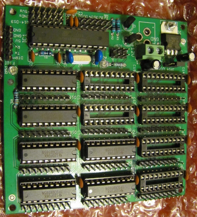
If you can separate them back to common anode, then my shift register board with 12 TPIC6B595 was designed for LED strip scoreboards, up to 12 digits per board. Atmega328P included, just plug on a FTDI Basic to program it. http://www.crossroadsfencing.com/BobuinoRev17/
Wow, thanks for all the great ideas! I had heard of MOSFETs, but I always thought they were for audio amps and stuff like that. Cool option.
I think I really like the simplicity of the TPIC6B595 though. But as I look at sample circuits online, they all seem to have the LED's connected with the positive leads tied together.
I am using four shift registers to drive each digit. I haven't done anything with PWM, but I thought that there would be issues with brightness of the strips since they time share the display.
Unless I am incorrect about the TPIC6B595, I think I'll go with the MOSFETs. If someone could point me to a schematic where the TPIC6B595 is driving LEDs wired as common cathode that would be very helpful.
Nearly everything uses MOSFETs these days, and they are still used for audio, but in class-D
amps now, not as analog amplifiers (like the original 2SK133/2SJ48's of olden days).
PWM because a FET full off or full on generates very little heat. PWM lets you control brightness with full off/on switching. Use light sensor feedback and the board can try to maintain relative brightness of the digits to itself. It won't blaze in the dark or wash out in the light given bright led strips.
So, can you guys confirm for me that I can use the MOSFET with my common cathode LED strip lights? Perhaps point me to a schematic online and recommend a particular model?
MrGibbage:
Also, I have my scoreboard constructed, and I have all of the negative leads of the lights tied together, so whatever I change, I need to keep the lights with the common negative tied to ground.
Perhaps you should have asked for advice before doing it so wrong?
Virtually all RGB strips have the positive side common.
GoForSmoke:
There is also the ULN200x chips. They are packaged Darlington arrays with built-in protection. They're rated at 500mA per pin but I don't think more than 500mA total would be a good idea.
Oh, come on! Did you not read the original post? Why are you fixated on obsolete ICs?
OK, let's do the calcs. Five inches (actually, 12.5 cm, so 8 of those per metre) at 240 LEDs per metre, would be 30 LEDs, at 20 mA per LED that is 200 mA, so the TPIC6A595 would be the obvious choice - if only the display was correctly wired.
Not that it matters now, but I saw a tutorial where someone used the shift registers and transistors. I didn't know that there were better options. Then when I went to construct it, I tied all of the negatives together, as one would for virtually any other project. It didn't occur to me that this could be a big mistake. sigh. I just now looked at the display and there's not way to rewire it, so I guess I will just make another one. There were a few things I didn't like about it anyway, so I guess I'll just take it as a life lesson. Story of my life...
Clearly, the TPIC is the very best option, and when I rebuild, I'll go that route.
I really don't need any dimming option, so I really don't see the need to go PWM. The scoreboard is for ultimate frisbee and we only play in the daytime, so I'll need full bright all the time. In fact, I am a little worried that they may not be bright enough for very sunny days.
Ok, I just ordered all of the parts to make my new display. This time I will wire up all of the positive leads a single common +12v. I definitely want to go with the TPIC. Specifically, perhaps the TPIC6A595??? I will be powering 30 LEDs from LED strip lights for each segment, roughly 300mA. So if I am drawing the number 8, that would be 7 segments for a total of 2.1 amps. If my calculations are correct.
What I am really having trouble with is finding any appropriate schematic drawings of circuits using the TPIC. Like, how do I wire an LED to this thing??? Can someone point me to a good example circuit?