Hello everyone! An absolute newbie here. My team and I are trying to build a sensory Braille Reader using linear actuators. Although this is a project that's been done multiple times before, we're running into a lot of hardware relateed problems. To preface this, here is the list of components we are using:
- Linear Actuators: JF-0630B (12VDC, 2A)
- Arduino Uno R3
- 4-Channel Relay Modules: JQC-3F-05VDC-C
- Power is obtained from a direct power supply (wall plug point).
When we first began, we faced an issue with the overheating of the actuators, for which we decided to add in a cooling fan on the advice of a professor. Not sure to what extent this is actually helping since we have not been able to test the actuators working for a long period of time due to the other issues that have come up.
On trying to connect two actuators using the relay modules, we turned on the power supply while the circuit was connected to my laptop. Something in the circuit started to buzz and made a sort of distressed sound, and my laptop immediately shut down. When I powered it back up, the USB port it was connected to no longer worked and the microcontroller chip of the Arduino board began to heat up. That board stopped working and we've got another now. We tested the same circuit using a desktop CPU and that seemed to run just fine, but there is a slight buzzing sound, coming either from the Arduino board or the relays, we're not sure.
After talking to another professor, we realised it might be because the direct power supply coming in was of 12V, which the Arduino wouldn't be able to handle. It was suggested that we find a different microcontroller board, like a Raspberry Pi but that would be out of our budget.
Instead we were wondering if it would be smarter to buy linear actuators that only required 5VDC to activate (like this one: https://kitsguru.com/products/dc-5v-force-0-2n-5n-solenoid-pull-push-long-stroke-electromagnet-industrial-grade?variant=46374667976956&country=IN¤cy=INR&utm_medium=product_sync&utm_source=google&utm_content=sag_organic&utm_campaign=sag_organic&gad_source=1). Would that work better? Or is there any way to handle the back voltage in a way that doesn't damage any of our components or our laptops? We've also only been able to connect 2 linear actuators so far, is there any way we can safely connect all six required for a Braille Display?
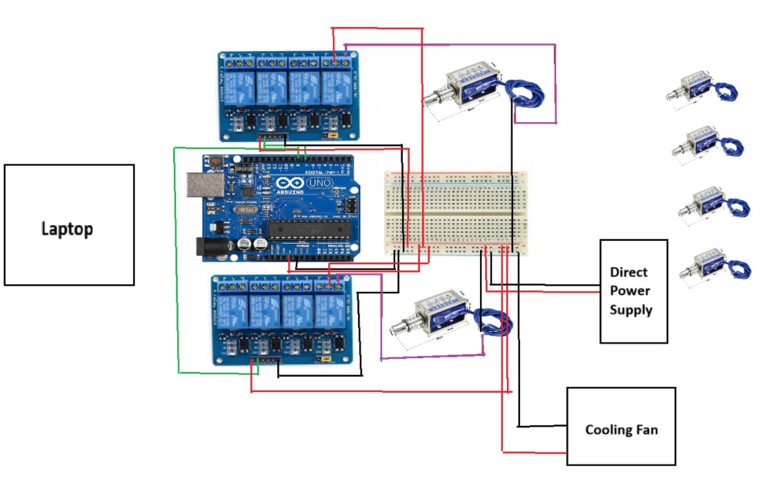
Attaching a very rough image of the circuit, if the connections aren't clear enough please let me know.
Any and all help is appreciated. Thanks for reading!