system
April 10, 2012, 7:29pm
1
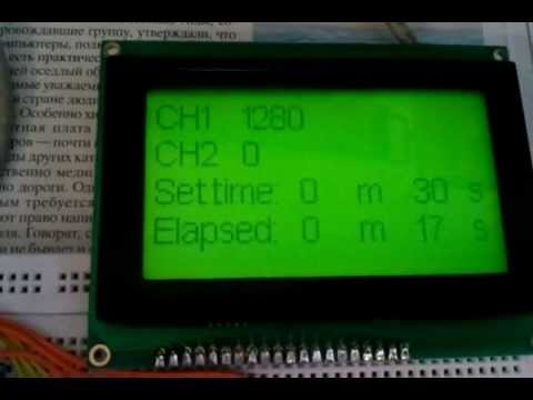
Hello. I need to make an impuls counter. So, earlier I solve the same task using inteprrupts. If its intersting, here is a demo videos:
and
Now I have to use something with more frequency. So, i know that ATMega has 3 timers. (one is using for delay). Please, help me to understand how to use them in "counter" mode. May be you have some examples, projects or tutorials. anithing for arduino.
I can't find someting good for arduino..
Thanks
MarkT
April 10, 2012, 11:07pm
2
Only timers 0 and 1 have their counter inputs connected to pins, and timer0 is used for millis() etc.
So use timer1, its counter input (T1) is hardwired to Arduino digital pin 5. Use counter mode 0100 (CTC mode) and set the clock source bits to 110 or 111 for falling and rising edge detection on T1 respectively. Read the counter value in TCNT1.
I think this is the right set-up, check the datasheet though.
  pinMode (5, INPUT) ;
  TCCR1A = 0x00 ;
  TCCR1B = 0x0E ; // or 0F for rising edge
  TCNT1 = 0 ;  // reset count
You'll lose PWM on pins 9 and 10 BTW.
Thereafter just read TCNT1 (which is 16 bits) for the current count value.
[edit: just tested my code, yes it works nicely
Osgeld
April 11, 2012, 5:18am
3
here is all the info you need to know about arduino timers
http://letsmakerobots.com/node/28278
attiny's work the same except the callback macro is different (if this really matters to you or not its good info)
ie
ISR(TIMER1_COMPA_vect)
on a tiny is
ISR(TIM1_COMPA_vect)
for whatever reason ... that cost me about an hour of head scratching (@#$!# grumble)
FilippovM:
I have some stuff about timers here:
system
April 11, 2012, 3:06pm
5
Very thanks!!!!!!
system
April 12, 2012, 11:37am
6
Hello. To test freq. counter i used Nick's code. But I remake it a bit, because it's easier to understand with only one Timer. So, my version:
// these are checked for in the main program
volatile boolean counterReady;

// internal to counting routine
unsigned long overflowCount;

void startCounting ()
{
  overflowCount = 0;            // no overflows yet

  // reset Timer 1
  TCCR1A = 0;
  TCCR1B = 0;

  // Timer 1 - counts events on pin D5
  TIMSK1 = _BV (TOIE1);   // interrupt on Timer 1 overflow

  TCNT1 = 0;      // counter to zero


  // Reset prescalers
  GTCCR = _BV (PSRASY);        // reset prescaler now
  // start Timer 1
  // External clock source on T1 pin (D5). Clock on rising edge.
  TCCR1B =  _BV (CS10) | _BV (CS11) | _BV (CS12);

}  // end of startCounting

ISR (TIMER1_OVF_vect)
{
  ++overflowCount;               // count number of Counter1 overflows
}  // end of TIMER1_OVF_vect


//******************************************************************
//  Timer2 Interrupt Service is invoked by hardware Timer 2 every 1ms = 1000 Hz
//  16Mhz / 128 / 125 = 1000 Hz

void setup ()
{
  Serial.begin(9600);
  startCounting();
  pinMode(10, OUTPUT);
} // end of setup

long res = 0;

void loop ()
{
  res = 65535*overflowCount + TCNT1;
  Serial.println(res);
  delay(500);
  digitalWrite(10,HIGH);
  delay(10);
  digitalWrite(10,LOW);
  delay(10);
}
I think it works OK. Thanks everyone!
system
April 12, 2012, 11:40am
7
in this program i use D10 as pulse generator to test the counter.
You used a couple of delays? Fair enough and nice and simple. Glad I was able to help.
system
April 13, 2012, 8:09am
9
Hello, Nick. Yes, it was the easiest way

