Hello. I am using this person library GitHub - JoaoLopesF/SPFD5408: Adafruit Libraries changed to works in TFT 2.4 shields with the SPFD5408 controller for Arduino Uno and Mega (Discontinued library), to run my 2.4 TFT LCD on my Arduino Mega 2560. The person code is set to use analog pin A0-A4 and digital pin 2-8, however i need to use the digital pin for another purpose and need to change digital pin 2-8 to digital pin 22-29. The person uses port to control the pin and i have no idea how to change it
#ifndef _pin_magic_
#define _pin_magic_
// This header file serves two purposes:
//
// 1) Isolate non-portable MCU port- and pin-specific identifiers and
// operations so the library code itself remains somewhat agnostic
// (PORTs and pin numbers are always referenced through macros).
//
// 2) GCC doesn't always respect the "inline" keyword, so this is a
// ham-fisted manner of forcing the issue to minimize function calls.
// This sometimes makes the library a bit bigger than before, but fast++.
// However, because they're macros, we need to be SUPER CAREFUL about
// parameters -- for example, write8(x) may expand to multiple PORT
// writes that all refer to x, so it needs to be a constant or fixed
// variable and not something like *ptr++ (which, after macro
// expansion, may increment the pointer repeatedly and run off into
// la-la land). Macros also give us fine-grained control over which
// operations are inlined on which boards (balancing speed against
// available program space).
// When using the TFT shield, control and data pins exist in set physical
// locations, but the ports and bitmasks corresponding to each vary among
// boards. A separate set of pin definitions is given for each supported
// board type.
// When using the TFT breakout board, control pins are configurable but
// the data pins are still fixed -- making every data pin configurable
// would be much too slow. The data pin layouts are not the same between
// the shield and breakout configurations -- for the latter, pins were
// chosen to keep the tutorial wiring manageable more than making optimal
// use of ports and bitmasks. So there's a second set of pin definitions
// given for each supported board.
// Shield pin usage:
// LCD Data Bit : 7 6 5 4 3 2 1 0
// Digital pin #: 7 6 13 4 11 10 9 8
// Uno port/pin : PD7 PD6 PB5 PD4 PB3 PB2 PB1 PB0
// Mega port/pin: PH4 PH3 PB7 PG5 PB5 PB4 PH6 PH5
// Leo port/pin : PE6 PD7 PC7 PD4 PB7 PB6 PB5 PB4
// Due port/pin : PC23 PC24 PB27 PC26 PD7 PC29 PC21 PC22
// Breakout pin usage:
// LCD Data Bit : 7 6 5 4 3 2 1 0
// Uno dig. pin : 7 6 5 4 3 2 9 8
// Uno port/pin : PD7 PD6 PD5 PD4 PD3 PD2 PB1 PB0
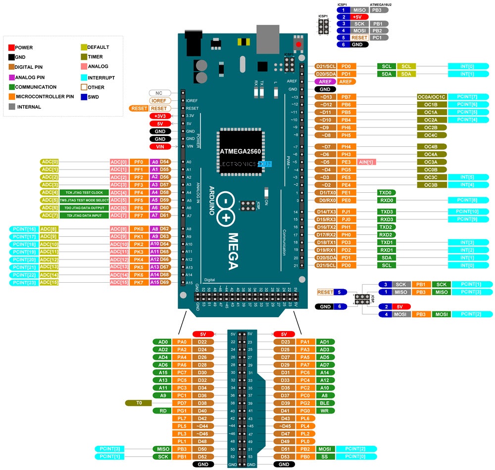
// Mega dig. pin: 29 28 27 26 25 24 23 22
// Mega port/pin: PA7 PA6 PA5 PA4 PA3 PA2 PA1 PA0 (one contiguous PORT)
// Leo dig. pin : 7 6 5 4 3 2 9 8
// Leo port/pin : PE6 PD7 PC6 PD4 PD0 PD1 PB5 PB4
// Due dig. pin : 40 39 38 37 36 35 34 33
// Due port/pin : PC8 PC7 PC6 PC5 PC4 PC3 PC2 PC1 (one contiguous PORT. -ish…)
// Modified for SPFD5408 by Joao Lopes to work with SPFD5408
// Pixel read operations require a minimum 400 nS delay from RD_ACTIVE
// to polling the input pins. At 16 MHz, one machine cycle is 62.5 nS.
// This code burns 7 cycles (437.5 nS) doing nothing; the RJMPs are
// equivalent to two NOPs each, final NOP burns the 7th cycle, and the
// last line is a radioactive mutant emoticon.
#define DELAY7 \
asm volatile( \
"rjmp .+0" "\n\t" \
"rjmp .+0" "\n\t" \
"rjmp .+0" "\n\t" \
"nop" "\n" \
::);
#if defined(__AVR_ATmega168__) || defined(__AVR_ATmega328P__) || defined (__AVR_ATmega328__) || defined(__AVR_ATmega8__)
// Arduino Uno, Duemilanove, etc.
#ifdef USE_ADAFRUIT_SHIELD_PINOUT
// LCD control lines:
// RD (read), WR (write), CD (command/data), CS (chip select)
#define RD_PORT PORTC /*pin A0 */
#define WR_PORT PORTC /*pin A1 */
#define CD_PORT PORTC /*pin A2 */
#define CS_PORT PORTC /*pin A3 */
#define RD_MASK B00000001
#define WR_MASK B00000010
#define CD_MASK B00000100
#define CS_MASK B00001000
// These are macros for I/O operations...
// Write 8-bit value to LCD data lines
#define write8inline(d) { \
PORTD = (PORTD & B00101111) | ((d) & B11010000); \
PORTB = (PORTB & B11010000) | ((d) & B00101111); \
WR_STROBE; } // STROBEs are defined later
// Read 8-bit value from LCD data lines. The signle argument
// is a destination variable; this isn't a function and doesn't
// return a value in the conventional sense.
#define read8inline(result) { \
RD_ACTIVE; \
DELAY7; \
result = (PIND & B11010000) | (PINB & B00101111); \
RD_IDLE; }
// These set the PORT directions as required before the write and read
// operations. Because write operations are much more common than reads,
// the data-reading functions in the library code set the PORT(s) to
// input before a read, and restore them back to the write state before
// returning. This avoids having to set it for output inside every
// drawing method. The default state has them initialized for writes.
#define setWriteDirInline() { DDRD |= B11010000; DDRB |= B00101111; }
#define setReadDirInline() { DDRD &= ~B11010000; DDRB &= ~B00101111; }
#else // Uno w/Breakout board
#define write8inline(d) { \
PORTD = (PORTD & B00000011) | ((d) & B11111100); \
PORTB = (PORTB & B11111100) | ((d) & B00000011); \
WR_STROBE; }
#define read8inline(result) { \
RD_ACTIVE; \
DELAY7; \
result = (PIND & B11111100) | (PINB & B00000011); \
RD_IDLE; }
#define setWriteDirInline() { DDRD |= B11111100; DDRB |= B00000011; }
#define setReadDirInline() { DDRD &= ~B11111100; DDRB &= ~B00000011; }
#endif
// As part of the inline control, macros reference other macros...if any
// of these are left undefined, an equivalent function version (non-inline)
// is declared later. The Uno has a moderate amount of program space, so
// only write8() is inlined -- that one provides the most performance
// benefit, but unfortunately also generates the most bloat. This is
// why only certain cases are inlined for each board.
#define write8 write8inline
#elif defined(__AVR_ATmega1281__) || defined(__AVR_ATmega2561__) || defined(__AVR_ATmega2560__) || defined(__AVR_ATmega1280__)
// Arduino Mega, ADK, etc.
#ifdef USE_ADAFRUIT_SHIELD_PINOUT
#define RD_PORT PORTF
#define WR_PORT PORTF
#define CD_PORT PORTF
#define CS_PORT PORTF
#define RD_MASK B00000001
#define WR_MASK B00000010
#define CD_MASK B00000100
#define CS_MASK B00001000
#define write8inline(d) { \
PORTH = (PORTH&B10000111)|(((d)&B11000000)>>3)|(((d)&B00000011)<<5); \
PORTB = (PORTB&B01001111)|(((d)&B00101100)<<2); \
PORTG = (PORTG&B11011111)|(((d)&B00010000)<<1); \
WR_STROBE; }
#define read8inline(result) { \
RD_ACTIVE; \
DELAY7; \
result = ((PINH & B00011000) << 3) | ((PINB & B10110000) >> 2) | \
((PING & B00100000) >> 1) | ((PINH & B01100000) >> 5); \
RD_IDLE; }
#define setWriteDirInline() { \
DDRH |= B01111000; DDRB |= B10110000; DDRG |= B00100000; }
#define setReadDirInline() { \
DDRH &= ~B01111000; DDRB &= ~B10110000; DDRG &= ~B00100000; }
#else // Mega w/Breakout board
// *** SPFD5408 change -- Begin
/* Original code commented
#define write8inline(d) { PORTA = (d); WR_STROBE; }
#define read8inline(result) { \
RD_ACTIVE; \
DELAY7; \
result = PINA; \
RD_IDLE; }
*/
// Changed to works with SPFD5408, based in post by Buhosoft (http://forum.arduino.cc/index.php?topic=292777.0)
#define write8inline(d) { \
PORTE = (PORTE & B11001111) | ((d << 2) & B00110000); \
PORTE = (PORTE & B11110111) | ((d >> 2) & B00001000); \
PORTG = (PORTG & B11011111) | ((d << 1) & B00100000); \
PORTH = (PORTH & B11100111) | ((d >> 3) & B00011000); \
PORTH = (PORTH & B10011111) | ((d << 5) & B01100000); \
WR_STROBE; }
#define read8inline(result) { \
RD_ACTIVE; \
DELAY7; \
result = ((PINH & B00011000) << 3) | ((PINE & B00001000) << 2) | ((PING & B00100000) >> 1) |((PINE & B00110000) >> 2) | ((PINH & B01100000) >> 5); \
RD_IDLE; }
#define setWriteDirInline() { DDRE |= B00111000; DDRG |= B00100000; DDRH |= B01111000;}
#define setReadDirInline() { DDRE &= ~B00111000; DDRG &= ~B00100000; DDRH &= ~B01111000;}
// -- End
#endif
// All of the functions are inlined on the Arduino Mega. When using the
// breakout board, the macro versions aren't appreciably larger than the
// function equivalents, and they're super simple and fast. When using
// the shield, the macros become pretty complicated...but this board has
// so much code space, the macros are used anyway. If you need to free
// up program space, some macros can be removed, at a minor cost in speed.
#define write8 write8inline
#define read8 read8inline
#define setWriteDir setWriteDirInline
#define setReadDir setReadDirInline
#define writeRegister8 writeRegister8inline
#define writeRegister16 writeRegister16inline
#define writeRegisterPair writeRegisterPairInline
#elif defined(__AVR_ATmega32U4__)
// Arduino Leonardo
#ifdef USE_ADAFRUIT_SHIELD_PINOUT
#define RD_PORT PORTF
#define WR_PORT PORTF
#define CD_PORT PORTF
#define CS_PORT PORTF
#define RD_MASK B10000000
#define WR_MASK B01000000
#define CD_MASK B00100000
#define CS_MASK B00010000
#define write8inline(d) { \
PORTE = (PORTE & B10111111) | (((d) & B10000000)>>1); \
PORTD = (PORTD & B01101111) | (((d) & B01000000)<<1) | ((d) & B00010000); \
PORTC = (PORTC & B01111111) | (((d) & B00100000)<<2); \
PORTB = (PORTB & B00001111) | (((d) & B00001111)<<4); \
WR_STROBE; }
#define read8inline(result) { \
RD_ACTIVE; \
DELAY7; \
result = ((PINE & B01000000) << 1) | ((PIND & B10000000) >> 1) | \
((PINC & B10000000) >> 2) | ((PINB & B11110000) >> 4) | \
(PIND & B00010000); \
RD_IDLE; }
#define setWriteDirInline() { \
DDRE |= B01000000; DDRD |= B10010000; \
DDRC |= B10000000; DDRB |= B11110000; }
#define setReadDirInline() { \
DDRE &= ~B01000000; DDRD &= ~B10010000; \
DDRC &= ~B10000000; DDRB &= ~B11110000; }
#else // Leonardo w/Breakout board
#define write8inline(d) { \
uint8_t dr1 = (d) >> 1, dl1 = (d) << 1; \
PORTE = (PORTE & B10111111) | (dr1 & B01000000); \
PORTD = (PORTD & B01101100) | (dl1 & B10000000) | (((d) & B00001000)>>3) |\
(dr1 & B00000010) | ((d) & B00010000); \
PORTC = (PORTC & B10111111) | (dl1 & B01000000); \
PORTB = (PORTB & B11001111) |(((d) & B00000011)<<4); \
WR_STROBE; }
#define read8inline(result) { \
RD_ACTIVE; \
DELAY7; \
result = (((PINE & B01000000) | (PIND & B00000010)) << 1) | \
(((PINC & B01000000) | (PIND & B10000000)) >> 1) | \
((PIND & B00000001) << 3) | ((PINB & B00110000) >> 4) | \
(PIND & B00010000); \
RD_IDLE; }
#define setWriteDirInline() { \
DDRE |= B01000000; DDRD |= B10010011; \
DDRC |= B01000000; DDRB |= B00110000; }
#define setReadDirInline() { \
DDRE &= ~B01000000; DDRD &= ~B10010011; \
DDRC &= ~B01000000; DDRB &= ~B00110000; }
#endif
// On the Leonardo, only the write8() macro is used -- though even that
// might be excessive given the code size and available program space
// on this board. You may need to disable this to get any sizable
// program to compile.
#define write8 write8inline
#elif defined(__SAM3X8E__)
// Arduino Due
#ifdef USE_ADAFRUIT_SHIELD_PINOUT
#define RD_PORT PIOA /*pin A0 */
#define WR_PORT PIOA /*pin A1 */
#define CD_PORT PIOA /*pin A2 */
#define CS_PORT PIOA /*pin A3 */
#define RD_MASK 0x00010000
#define WR_MASK 0x01000000
#define CD_MASK 0x00800000
#define CS_MASK 0x00400000
#define write8inline(d) { \
PIO_Set(PIOD, (((d) & 0x08)<<(7-3))); \
PIO_Clear(PIOD, (((~d) & 0x08)<<(7-3))); \
PIO_Set(PIOC, (((d) & 0x01)<<(22-0)) | (((d) & 0x02)<<(21-1))| (((d) & 0x04)<<(29-2))| (((d) & 0x10)<<(26-4))| (((d) & 0x40)<<(24-6))| (((d) & 0x80)<<(23-7))); \
PIO_Clear(PIOC, (((~d) & 0x01)<<(22-0)) | (((~d) & 0x02)<<(21-1))| (((~d) & 0x04)<<(29-2))| (((~d) & 0x10)<<(26-4))| (((~d) & 0x40)<<(24-6))| (((~d) & 0x80)<<(23-7))); \
PIO_Set(PIOB, (((d) & 0x20)<<(27-5))); \
PIO_Clear(PIOB, (((~d) & 0x20)<<(27-5))); \
WR_STROBE; }
#define read8inline(result) { \
RD_ACTIVE; \
delayMicroseconds(1); \
result = (((PIOC->PIO_PDSR & (1<<23)) >> (23-7)) | ((PIOC->PIO_PDSR & (1<<24)) >> (24-6)) | \
((PIOB->PIO_PDSR & (1<<27)) >> (27-5)) | ((PIOC->PIO_PDSR & (1<<26)) >> (26-4)) | \
((PIOD->PIO_PDSR & (1<< 7)) >> ( 7-3)) | ((PIOC->PIO_PDSR & (1<<29)) >> (29-2)) | \
((PIOC->PIO_PDSR & (1<<21)) >> (21-1)) | ((PIOC->PIO_PDSR & (1<<22)) >> (22-0))); \
RD_IDLE;}
#define setWriteDirInline() { \
PIOD->PIO_MDDR |= 0x00000080; /*PIOD->PIO_SODR = 0x00000080;*/ PIOD->PIO_OER |= 0x00000080; PIOD->PIO_PER |= 0x00000080; \
PIOC->PIO_MDDR |= 0x25E00000; /*PIOC->PIO_SODR = 0x25E00000;*/ PIOC->PIO_OER |= 0x25E00000; PIOC->PIO_PER |= 0x25E00000; \
PIOB->PIO_MDDR |= 0x08000000; /*PIOB->PIO_SODR = 0x08000000;*/ PIOB->PIO_OER |= 0x08000000; PIOB->PIO_PER |= 0x08000000; }
#define setReadDirInline() { \
pmc_enable_periph_clk( ID_PIOD ) ; pmc_enable_periph_clk( ID_PIOC ) ; pmc_enable_periph_clk( ID_PIOB ) ; \
PIOD->PIO_PUDR |= 0x00000080; PIOD->PIO_IFDR |= 0x00000080; PIOD->PIO_ODR |= 0x00000080; PIOD->PIO_PER |= 0x00000080; \
PIOC->PIO_PUDR |= 0x25E00000; PIOC->PIO_IFDR |= 0x25E00000; PIOC->PIO_ODR |= 0x25E00000; PIOC->PIO_PER |= 0x25E00000; \
PIOB->PIO_PUDR |= 0x08000000; PIOB->PIO_IFDR |= 0x08000000; PIOB->PIO_ODR |= 0x08000000; PIOB->PIO_PER |= 0x08000000; }
// Control signals are ACTIVE LOW (idle is HIGH)
// Command/Data: LOW = command, HIGH = data
// These are single-instruction operations and always inline
#define RD_ACTIVE RD_PORT->PIO_CODR |= RD_MASK
#define RD_IDLE RD_PORT->PIO_SODR |= RD_MASK
#define WR_ACTIVE WR_PORT->PIO_CODR |= WR_MASK
#define WR_IDLE WR_PORT->PIO_SODR |= WR_MASK
#define CD_COMMAND CD_PORT->PIO_CODR |= CD_MASK
#define CD_DATA CD_PORT->PIO_SODR |= CD_MASK
#define CS_ACTIVE CS_PORT->PIO_CODR |= CS_MASK
#define CS_IDLE CS_PORT->PIO_SODR |= CS_MASK
#else // Due w/Breakout board
#define write8inline(d) { \
PIO_Set(PIOC, (((d) & 0xFF)<<1)); \
PIO_Clear(PIOC, (((~d) & 0xFF)<<1)); \
WR_STROBE; }
#define read8inline(result) { \
RD_ACTIVE; \
delayMicroseconds(1); \
result = ((PIOC->PIO_PDSR & 0x1FE) >> 1); \
RD_IDLE;}
#define setWriteDirInline() { \
PIOC->PIO_MDDR |= 0x000001FE; /*PIOC->PIO_SODR |= 0x000001FE;*/ PIOC->PIO_OER |= 0x000001FE; PIOC->PIO_PER |= 0x000001FE; }
#define setReadDirInline() { \
pmc_enable_periph_clk( ID_PIOC ) ; \
PIOC->PIO_PUDR |= 0x000001FE; PIOC->PIO_IFDR |= 0x000001FE; PIOC->PIO_ODR |= 0x000001FE; PIOC->PIO_PER |= 0x000001FE; }
// When using the TFT breakout board, control pins are configurable.
#define RD_ACTIVE rdPort->PIO_CODR |= rdPinSet //PIO_Clear(rdPort, rdPinSet)
#define RD_IDLE rdPort->PIO_SODR |= rdPinSet //PIO_Set(rdPort, rdPinSet)
#define WR_ACTIVE wrPort->PIO_CODR |= wrPinSet //PIO_Clear(wrPort, wrPinSet)
#define WR_IDLE wrPort->PIO_SODR |= wrPinSet //PIO_Set(wrPort, wrPinSet)
#define CD_COMMAND cdPort->PIO_CODR |= cdPinSet //PIO_Clear(cdPort, cdPinSet)
#define CD_DATA cdPort->PIO_SODR |= cdPinSet //PIO_Set(cdPort, cdPinSet)
#define CS_ACTIVE csPort->PIO_CODR |= csPinSet //PIO_Clear(csPort, csPinSet)
#define CS_IDLE csPort->PIO_SODR |= csPinSet //PIO_Set(csPort, csPinSet)
#endif
#else
#error "Board type unsupported / not recognized"
#endif
#if !defined(__SAM3X8E__)
// Stuff common to all Arduino AVR board types:
#ifdef USE_ADAFRUIT_SHIELD_PINOUT
// Control signals are ACTIVE LOW (idle is HIGH)
// Command/Data: LOW = command, HIGH = data
// These are single-instruction operations and always inline
#define RD_ACTIVE RD_PORT &= ~RD_MASK
#define RD_IDLE RD_PORT |= RD_MASK
#define WR_ACTIVE WR_PORT &= ~WR_MASK
#define WR_IDLE WR_PORT |= WR_MASK
#define CD_COMMAND CD_PORT &= ~CD_MASK
#define CD_DATA CD_PORT |= CD_MASK
#define CS_ACTIVE CS_PORT &= ~CS_MASK
#define CS_IDLE CS_PORT |= CS_MASK
#else // Breakout board
// When using the TFT breakout board, control pins are configurable.
#define RD_ACTIVE *rdPort &= rdPinUnset
#define RD_IDLE *rdPort |= rdPinSet
#define WR_ACTIVE *wrPort &= wrPinUnset
#define WR_IDLE *wrPort |= wrPinSet
#define CD_COMMAND *cdPort &= cdPinUnset
#define CD_DATA *cdPort |= cdPinSet
#define CS_ACTIVE *csPort &= csPinUnset
#define CS_IDLE *csPort |= csPinSet
#endif
#endif
// Data write strobe, ~2 instructions and always inline
#define WR_STROBE { WR_ACTIVE; WR_IDLE; }
// These higher-level operations are usually functionalized,
// except on Mega where's there's gobs and gobs of program space.
// Set value of TFT register: 8-bit address, 8-bit value
#define writeRegister8inline(a, d) { \
CD_COMMAND; write8(a); CD_DATA; write8(d); }
// Set value of TFT register: 16-bit address, 16-bit value
// See notes at top about macro expansion, hence hi & lo temp vars
#define writeRegister16inline(a, d) { \
uint8_t hi, lo; \
hi = (a) >> 8; lo = (a); CD_COMMAND; write8(hi); write8(lo); \
hi = (d) >> 8; lo = (d); CD_DATA ; write8(hi); write8(lo); }
// Set value of 2 TFT registers: Two 8-bit addresses (hi & lo), 16-bit value
#define writeRegisterPairInline(aH, aL, d) { \
uint8_t hi = (d) >> 8, lo = (d); \
CD_COMMAND; write8(aH); CD_DATA; write8(hi); \
CD_COMMAND; write8(aL); CD_DATA; write8(lo); }
#endif // _pin_magic_
