Direction is quite easy then. I actually made an Instructable about this, but I'll spare you the trouble.
int in1pin = 6; // pins to h-bridge
int in2pin = 7;

int leftButton = 8;
int rightButton = 9; // buttons

void setup() {

  pinMode(in1pin, OUTPUT);
  pinMode(in2pin, OUTPUT); // outputs

  pinMode(leftButton, INPUT_PULLUP);
  pinMode(rightButton, INPUT_PULLUP); // inputs w internal pullup resistors

}

void loop() {

  int leftPinState = digitalRead(leftButton);
  int rightPinState = digitalRead(rightButton); // set value names for read data

  if (leftPinState == LOW) { // if left button is pressed ...

    digitalWrite(in1pin, HIGH); // make motor go one way
    digitalWrite(in2pin, LOW);

  }

  else if (rightPinState == LOW) { // if right button is pressed ...

    digitalWrite(in1pin, LOW);
    digitalWrite(in2pin, HIGH); // make motor go other way


  }

  else { // if neither button is pressed ...

    digitalWrite(in1pin, LOW); // nothing happens
    digitalWrite(in2pin, LOW);

  }

}
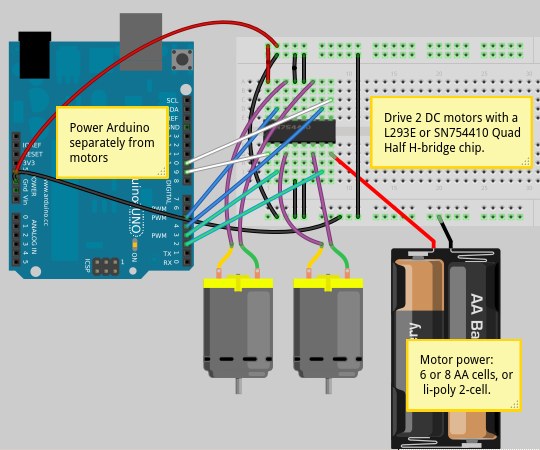
That is a code controlling one DC motor with an H-Bridge that I found in my old sketchbook. While you press one button, the motor will turn one way. If you press the other button, it will turn the other way. Here is also a diagram of my setup.
or something like that. Also, delays aren't the best thing to use, but I suppose for this project it is fine if all you are doing is controlling those motors.
All you need in void setup() is to set the pins you connected to your h-bridge as outputs. I'd suggest to give good names so you can tell which pin does what -
int M1clockwise = 6;
int M1cclockwise = 7; // motor 1

int M2clockwise = 8;
int M2cclockwise = 9; // motor 2

void setup() {

  pinMode(M1clockwise, OUTPUT);
  pinMode(M1cclockwise, OUTPUT);

  pinMode(M2clockwise, OUTPUT);
  pinMode(M2cclockwise, OUTPUT);

}
Obviously your code needs to match the pins that you are actually connecting, of course.

Also, the two white wires in your diagram going to the arduino board actually can just lead to the power rails, since you aren't interested in changing speed at all.
or something like that. Also, delays aren't the best thing to use, but I suppose for this project it is fine if all you are doing is controlling those motors.
Do you really want both in2pin and in1pin HIGH after the 750ms delay?
chummer1010:
I actually made an Instructable about this, but I'll spare you the trouble.
Caught red handed.
How did you power the Arduino.
Did you calculate for the 2-3volt drop of the L293 (2-3volt left for the motor).
Is the stall current of that motor going to overheat or damage the onboard 5volt regulator or trip the USB fuse.
Not wise to power a motor from the 5volt pin (= MCU supply), unless it's a tiny one.
Leo..
chummer1010:
All you need in void setup() is to set the pins you connected to your h-bridge as outputs. I'd suggest to give good names so you can tell which pin does what -
int M1clockwise = 6;
int M1cclockwise = 7; // motor 1
int M2clockwise = 8;
int M2cclockwise = 9; // motor 2
Obviously your code needs to match the pins that you are actually connecting, of course.
Also, the two white wires in your diagram going to the arduino board actually can just lead to the power rails, since you aren't interested in changing speed at all.
Alright so I got this inside the code now, what should go inside of the loop so I can start making the delays and changing direction?
How did you power the Arduino.
Did you calculate for the 2-3volt drop of the L293 (2-3volt left for the motor).
Is the stall current of that motor going to overheat or damage the onboard 5volt regulator or trip the USB fuse.
Not wise to power a motor from the 5volt pin (= MCU supply), unless it's a tiny one.
Leo..
I actually used a 9V battery, however I failed to mention that I see.
@GarrisonFord , here is an example of what your code could look like, I tried to explain things as best as I could.
int M1clockwise = 6;
int M1cclockwise = 7; // motor 1

int M2clockwise = 8;
int M2cclockwise = 9; // motor 2

void setup() {

  pinMode(M1clockwise, OUTPUT);
  pinMode(M1cclockwise, OUTPUT);

  pinMode(M2clockwise, OUTPUT);
  pinMode(M2cclockwise, OUTPUT); // set the pins as outputs

}

void loop() {

  digitalWrite(M1clockwise, HIGH); // part 1
  delay(500);
  digitalWrite(M1clockwise, LOW);
  // make one motor turn clockwise for .5 secs, then turn off

  digitalWrite(M1cclockwise, HIGH); // part 2
  delay(150);
  digitalWrite(M1cclockwise, LOW);
  // make same motor turn for .15 secs in counterclockwise, then turn around

  digitalWrite(M2cclockwise, HIGH); // part 3
  delay(600);
  digitalWrite(M2cclockwise, LOW);
  // make other motor turn counterclockwise for .6 secs, then turn off

  /* note that since we're in void loop, after 'part 3',
   * part 1 will happen right after,
   * and this process will be looped forever
   * until a power supply is cut,
   * or there is something within the code to stop it
   */
}
How did you power the Arduino.
Did you calculate for the 2-3volt drop of the L293 (2-3volt left for the motor).
Is the stall current of that motor going to overheat or damage the onboard 5volt regulator or trip the USB fuse.
Not wise to power a motor from the 5volt pin (= MCU supply), unless it's a tiny one.
Leo..
I actually built this robot the same way a year ago and it worked perfectly with 4 AA Batteries powering up both the arduino and the motors.
A 9volt smoke alarm battery to power an Arduino and a motor.
Double fail.
4AA batteries Which ones.
If you connect the 4AA batteries directly to the motor chip and to the 5volt pin of the Arduino, then the motor current is not coming from or flowing through the Arduino.
Leo..
Wawa:
A 9volt smoke alarm battery to power an Arduino and a motor.
Double fail.
plugging a 9V into the Vin pin on the arduino and the h bridge to 5V works fine for me. it's also how i was instructed to work with the motor I have. Of course, all motors are different, aren't they?
How should I have done it? It'd be helpful to know why I was wrong instead of just knowing that I'm wrong and feeling dumb about it.
Allow me to clarify, when I said that "I built it" I meant that I built it in that course I previously talked about, getting help to code and wire it up. Now, a year after, I do not remember everything in programming or wiring.
