Need help with KS0108 GLCD and U∞g2 library

Hello, i got a blue-backlight KS0108 GLCD almost 6 months ago, i have used openGLCD, KS0108_GLCD before to make this work but those were very inneficient, and i want to try a new library called U∞g2.

I asked one of my friends who is a pro at software to write an example code for U∞g2 library and he made this code:

#include <U8g2lib.h>

U8G2_KS0108_128X64_F u8g2(U8G2_R0, A3, 2, 3, 4, 5, 6, 7, 8, 9, 10, A0, A1, A2,  11);
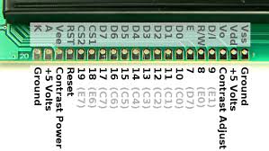
/*Since your pinout is 
IO A0
RW A1
E A2
DB0 A3
DB1 2
DB2 3
DB3 4
DB4 5
DB5 6
DB6 7
DB7 8
CS1 9
CS2 10
RST 11
*/

void setup() {
  u8g2.begin(); //Start it up
  delay(500); //Wait for it
  u8g2.clearBuffer(); //Kind of like lcd.clear
  u8g2.setFont(u8g2_font_6x12_tr); //I chose a 6x12 Turkish font, since you're Turkish
  u8g2.drawStr(10, 30, "wanna win a million?"); //It displays the text at x10 y30
  u8g2.sendBuffer(); //It's kinda like 'display.display();' on Adafruit libraries.
}

void loop() {
  // No need to update
}

He told me that he followed my pinout and it worked on his side, what could be the culprit of it not working?

Also, here's what i can confirm:

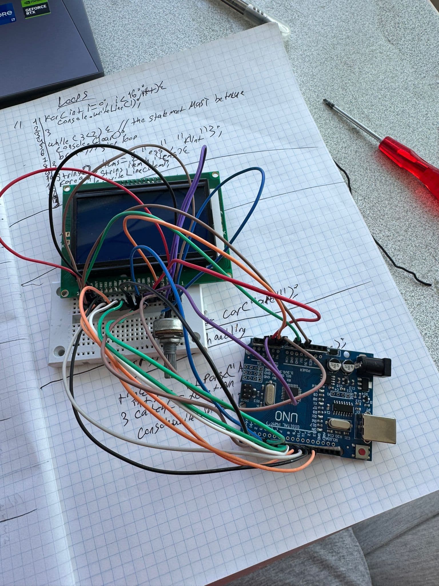
  • Cables, wiring, potentiometer and diagram are correct
  • Code is correct (maybe)
  • The backlight turns on
  • The GLCD has worked before
  • I can see the contrast adjusting as i turn the potentiometer

Here are the parts i got:
M-M jumpers (idk how many)
10K potentiometer
Medium sized breadboard (It had some contact resistance burns, didn't use those parts.)
Arduino uno (Ch340), extra note; it feels like it's gonna explode if i look at it wrong, but it could be just me.

I'd like to hear some opinions and possible fixes from you awesome people here.

Exchange the red and black wires with the blue and yellow, that might do something. The chances of getting some good help is poor unless we know what you have. Also burnt parts tells me you are working with junk.

Post an annotated schematic showing exactly how you have wired this, including power, ground, power sources etc. Post links to technical information on the hardware items. I would like to know what processor you are using,

What do you mean red, black, blue and yellow, which pins are those, can you specify?

Also, unfortunately my camera broke but i can give you an image of my drawing of where is connected where, later (not now)

Take a close look at the schematic and pictures you did not post. I could be imagining the wrong ones.

Also just so you know, i did NOT use the burnt part.

But here's the photo from my backup phone

Nice photo but to cluttered for my old eyes to follow. Posting the schematic (diagram) will be the next thing you need to do.

the + and - for the backlight and vss and vdd are the same
di is at a0
rw is at a1
e is at a2
db0 is a3
db1 is 2
db2 is 3
db3 is 4
db4 is 5
db5 is 6
db6 is 7
db7 is 8
cs1 is 9
cs2 is 10
rst is 11
and the rest are connected accordingly to the schematic,
VOUT and CONTRAST is connected to a pot

And where is it?

I didn't say schematic as like a circuit diagram, i meant like accordingly for the potentiometer. Sorry for the confusion

Always use an example code from the library to test if your display is not faulty and wiring is correct. If all is well, then try your own/friend's code.

Seems like my lcd isn't compatible with it.

I have used KS0108 GLCD with U8G2, they are compatible.