It's much more likely that the LEDs were deficient than the IC or the module. By the way, no thread is too long if progress is actually being made. It's been interesting to follow. Keep up the good work.
I am now able to use the 9V DC adapter again to power the circuit. Originally, using it caused the LEDs in the matrix to flicker visibly. Now, that is no longer the case. I am still using the same voltage regulator module as before, so it wasn't the problem. So it is possible it was an issue with the HT16K33 module I originally used (the Aadfruit module). I don't see how it could have been the LEDs themselves, as they were being controlled by the HT16K33 module.
The LEDs are now at the brightness level I wanted; bright enough to see clearly, but not too bright that they would need to be dimmed in low light or the dark.
I have started to build a button array to control the clock functions, and am using momentary contact buttons that have a LED built-in to the button cap. They are color-coded for function so they don't need to be labelled. I had a bunch of them that I purchased several years ago for a project that needed illuminated buttons, so they came in handy. The LED is separate from the switch, so no chance of interference with the button function. I haven't found much information on how to connect the buttons to the Nano, other than an analog pin is used for input (any available pin, I assume) and a resister is also needed for each button. What value resistor, and where they connect to the button is what I am trying to find out. Here is a picture of the button array I built;
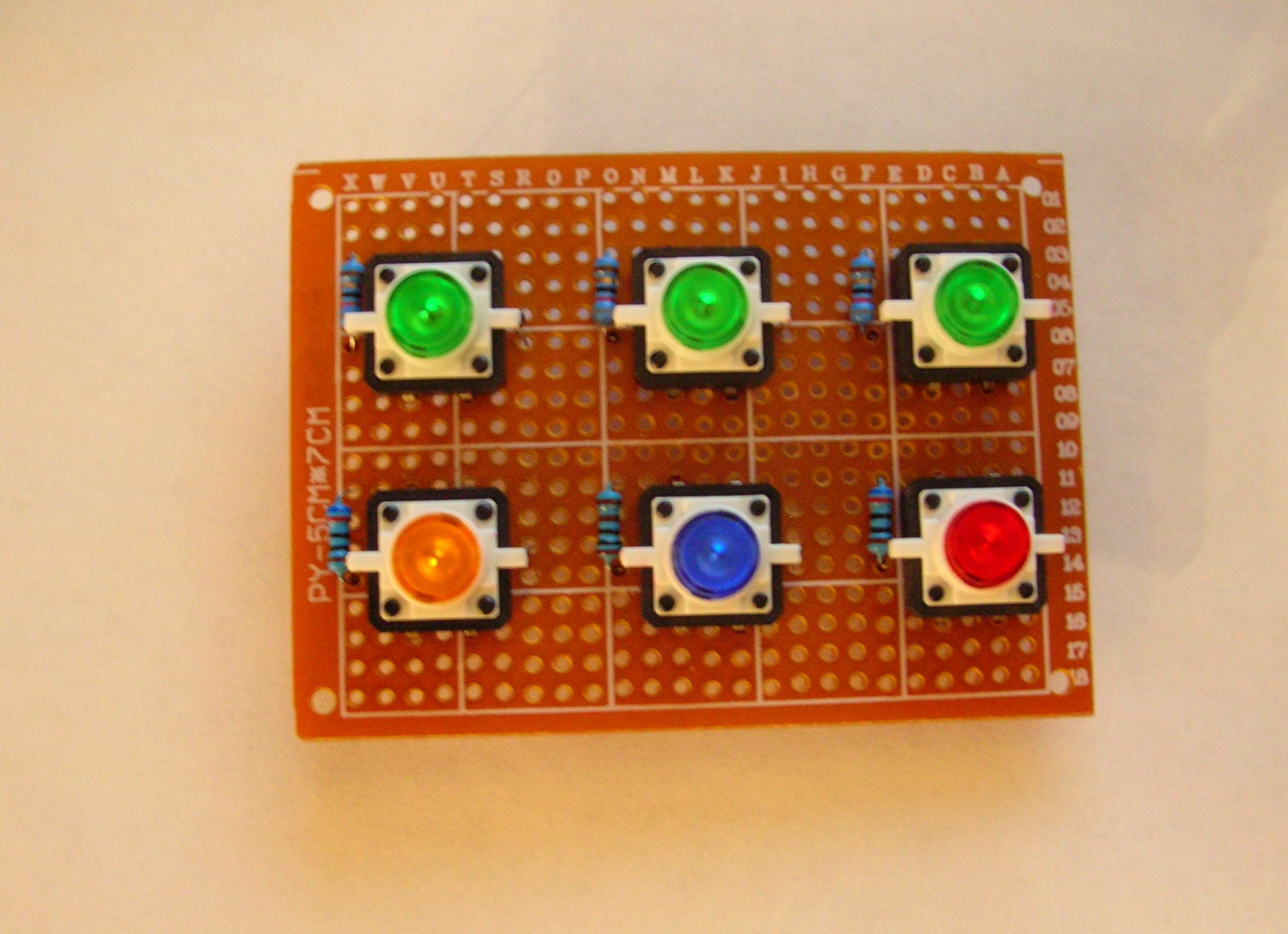
The resistors next to each button is for the built-in LED.
I haven't found much information on how to connect the buttons to the Nano, other than an analog pin is used for input (any available pin, I assume) and a resister is also needed for each button.
Digital pin. You can use the internal pull up resistor and save yourself the parts.
i thought the plan was to connect the buttons to the ht16k33. The extra leds could be connected to the ht chip also, so no series resistors would be needed. There's a diagram on page 17 of the data sheet. Looks quite straight forward. it says you will need a diode in series with each switch.
PaulRB:
i thought the plan was to connect the buttons to the ht16k33.
It was. But since I rewired the matrix so all 5 of the LED rows would be included, I had to use all of the anode and cathode pins on the HT16K33 module. The LEDs in the buttons will be powered form the remaining set of output pins on the voltage regulator. They will be on all the time the clock circuit is connected to power. The updated schematic for the LED matrix is shown below;

I have made a number of changes to the original design due to input from you and others, and because of problems that needed another approach to solve. I did mention at the beginning that there probably would be changes as the project progressed; it is usually how things work out for me. The first time is never the last. I hope that you will continue to offer your support to this project.
jeredneus:
But since I rewired the matrix so all 5 of the LED rows would be included, I had to use all of the anode and cathode pins on the HT16K33 module.
Your schematic shows C7 and A15 unused? You could easily attach the button leds there. And attach the buttons themselves to the chip, even though all cathode/anodes are in use. Check out this project which has a 16 x 8 led matrix and 16 pushbuttons all connected to the ht chip.
Also I was wrong about having to connect a diode to each button. That's only if you need "n-key rollover" in other words you need to detect any number of simultaneous presses, like on a PC keyboard. For your simple clock-setting buttons, you will need only one or two diodes.
I checked out the link to the project you mentioned, and the buttons shown had a resistor attached to them. I didn't see any mention of diodes being used. The board used was the version designed for two 8x8 LED matrix modules, not the breakout version I am using. The datasheet for the HT16K33 chip, as well as the few examples I could find that referenced the keyscan function of the chip is way over my head.
If you could provide an example of where I would need to place the diodes you mentioned, as well as the type of diode, it would be appreciated.
It would be far simpler to use the Arduino pins for keys, if you have enough available.
Edit - you will thank me for this advice when you get to the software stage and discover that the Adafruit library doesn't support keys. ![]()
jeredneus:
I checked out the link to the project you mentioned, and the buttons shown had a resistor attached to them.
Yes, you're right. And the suggested circuits on page 34 of the ht16k33 data sheet also show them, so I've put them in my schematic.
jeredneus:
I didn't see any mention of diodes being used.
Correct again, the tetris project does not have them. But the data sheet does show them. So diode D1 in my schematic may or may not be needed. I put an IN4001 in just in case it is.
jeredneus:
The board used was the version designed for two 8x8 LED matrix modules, not the breakout version I am using.
Doesn't matter, its the same chip.
jeredneus:
The datasheet for the HT16K33 chip, as well as the few examples I could find that referenced the keyscan function of the chip is way over my head.
Datasheets are often difficult to follow. Have you read the data sheet for the AVR ATMega328? Has that stopped you using an Arduino? Me neither!
So, here's how I think you should connect up the 6 buttons and their leds:

And try this code for reading the keys:
#include <Wire.h>

void setup() {
  Serial.begin(9600);
  Wire.begin();
}

void loop() {

  Wire.beginTransmission(0x70);
  Wire.write(0x40);
  Wire.endTransmission();

  Wire.requestFrom(0x70, 1);
  while (Wire.available() < 1);
  Serial.println(Wire.read(), BIN);
}
aarg:
It would be far simpler to use the Arduino pins for keys, if you have enough available.
Edit - you will thank me for this advice when you get to the software stage and discover that the Adafruit library doesn't support keys.
Perhaps, but more interesting to get the ht16k33 to do it, I think!
Keeps those Arduino pins free for future enhancements, too. Why get a dog and bark yourself? ![]()
I did mention that the Adafruit library lacked code for reading keys back in post #30.
Could you please check my schematic, before jeredneus solders anything up?
PaulRB:
Datasheets are often difficult to follow. Have you read the data sheet for the AVR ATMega328? Has that stopped you using an Arduino? Me neither!
The only Arduino board I have used so far is the Nano, so I haven't read any datasheets on other Arduino boards. The only other board I will be using in the near future would be the Uno, as the deluxe starter kit I ordered, but haven't received yet, comes with an Uno board. The basic starter kit I first ordered never arrived (thank USPS for that!), so I am relying on Internet searches and help I have been receiving from this forum. Your schematic is very detailed, and I appreciate your effort. I was hoping not to have to wire anything else to the matrix, and the lack of software support for the keyscan function is a problem.
aarg:
It would be far simpler to use the Arduino pins for keys, if you have enough available.
Edit - you will thank me for this advice when you get to the software stage and discover that the Adafruit library doesn't support keys.
Seeing as I have only used four of the pins on the Nano; 5V, GND, A4 & A5, there are plenty of pins available. How long can the wires be from the buttons to the pins on the Nano without encountering interference in the circuit? The button array will be mounted in a box that will be outside the enclosure for the circuit on the back of the clock. The idea is to connect them to the circuit using a plug mounted on the exterior of the enclosure when making changes to the settings; I will also be adding a countdown function to the clock when I finish getting it to work as a regular clock. That is why I have six buttons. I appreciate your heads up on the lack of support for the key function in the Adafruit library. It will save time looking for something that is not available.
I entertained the idea of making the button array wireless, but wasn't sure how complicated that would be. It would need to be radio frequency (Bluetooth, maybe), not IR as the design of the clock frame would block an IR receiver sensor.
Quick reply - I've chosen IR as a control for my clocks. The current prototype has the IR receiver at the back - it picks up the reflection of the signal from whatever is behind it. I like this because the remote has all the buttons I will ever need, and is cheap and replaceable.
Generally, there is no big problem in running short wires to a plug as you describe. A fairly low value pull up resistor like 1.0k should prevent noise pickup. Six pins is not a huge burden if you are not using many pins for other things.
There may be other software somewhere for the HT16K33 other than the Adafruit, but I couldn't find any. Perhaps have another look around? It is possible to modify the library, but I don't think it is a beginner task.
It occurred to me that the datasheet for the HT16K33 is for just the chip, not the module; there looks like there is a diode on the circuit board next to the A12 pin, and just above it there are three resistors. These could be used for the button matrix; so the schematics in the datasheet are for the chip itself, not the module that contains the chip. Is that correct?
I was hoping not to have to wire anything else to the matrix
You would be wiring the buttons & leds to the ht16k33 board, you would not have to wire them to the matrix. (Electrically speaking they would be part of the matrix, of course, but phsically they would/could be entirely separate).
the lack of software support for the keyscan function is a problem.
You and aarg percieve it to be. I don't believe it will be a problem and have already proposed some simple code in my last post. It does not require changes to the library code. The availability of libraries in the Arduino IDE is a huge benefit to beginners, but it does lead to the myth that if the library for something lacks a certain feature or there is no library then "it can't be done" or "its not Arduino compatible".
I think it would be a shame to waste the Nano's pins running these switches & leds when you have a chip designed to do this already in your circuit.
jeredneus:
there looks like there is a diode on the circuit board next to the A12 pin, and just above it there are three resistors. These could be used for the button matrix; so the schematics in the datasheet are for the chip itself, not the module that contains the chip. Is that correct?
Yes, the data sheet is for the chip. The diode and resistors you refer to, and those 3 pairs of pads next to them on the board, are shown in the suggested circuit on page 34 of the data sheet. They are for setting the address on the i2c bus. The default is 0x70 but you can select 7 other addresses by shorting those pairs of pads with blobs of solder. This allows up to 8 of these chips to be connected to the i2c bus.
So if I wire the buttons to the ht16k33, I could still physically locate them externally from the clock circuit enclosure? Locating them on the enclosure would mean having to remove the clock from the wall to access the buttons, since there won't be much clearance between the clock back and the wall. The cable leading from the enclosure to the box containing the buttons would be permanently connected on the enclosure side, and could be secured behind the clock front for easy access to connect it to the button box.
I should have mentioned that the LEDs in the button caps are not all the same color; they are the same color as the button caps themselves (three green, one red, one blue and one yellow). I don't know what the specifications are for the LEDs, other than they are superbright chip LEDs. The only information I do have is on the switch specs. That was why I was going to power the LEDs separately. The green LEDs were not as bright as the red, blue and yellow, but were still brighter than I liked, so I tried different resistors until I found the values that would provide the brightness level that worked for each color (visibly lit, but not blinding). Unless it doesn't matter that they have limiting resistors, and won't affect the function of the matrix.
Hmm... Yes, but very long wires might cause signal timing problems due to cable capacitance. Don't know how long "very long" would be. You would have to try it. A short length of cat5 cable has 8 conductors, which would be enough for my suggested circuit. Remember that, as you found earlier, leds attached to the matrix are less bright than when attached directly to 5V (depending what value series resistors you use) so they might not be too bright anyway.
Attaching the leds to the matrix board may also solve the problem of the different colours having different brightness, because the constant-current outputs of the ht16k33 will adjust to give the same current. Same current does not guarantee same brightness, however, because different leds have differing efficiencies turning electrical power into light.
As for the IR remote control idea, you should check that your perspex/acrylic sheet does not block the IR signal. Hold a piece of it against the IR sensor on your TV and see if you can still change channel. If so, you could hide the sensor behind the sheet in your clock and it would make a neat solution.
I did some research on the Internet, and found this site - http://www.instructables.com/id/How-to-access-5-buttons-through-1-Arduino-input/ - which showed how to connect several buttons to one analog pin on the Arduino boards. By using the schematic that was supplied, I was able to wire the buttons so only two wires are needed for connecting to the Nano; 5V and A0 pin. The pull-down resistor is connected to the Nano directly. I tested the connection via a breadboard setup before soldering to confirm it will work, and it does. So I can use a section of a shielded USB cable to connect the button assembly to the PCB containing the components for the clock circuit; two wires for the buttons and the other two for the LEDs in the button caps. The resistors needed for the different color LEDs ranged from 75 ohms for the green to 3K for the red to create a uniform brightness for the four colors. I might still need to use a diode, but am not sure which end of the cable to connect it to; the button PCB or the clock PCB.
PaulRB:
As for the IR remote control idea, you should check that your perspex/acrylic sheet does not block the IR signal. Hold a piece of it against the IR sensor on your TV and see if you can still change channel. If so, you could hide the sensor behind the sheet in your clock and it would make a neat solution.
I tested the IR idea you suggested, but the tinted film covering the display blocked too much of the light for the sensor to work. I finally received the second Arduino starter kit I ordered, and it included a IR sensor and IR remote. I might still use it on the second clock project I started that will have a similar display as the wall clock I am currently building. the second clock uses the 5 x 7 LED matrix modules that I purchased when I started the original clock project back in January before I found I could build the LED matrix from scratch, so the display could be white. The LED modules are red, but they have square pixels instead of round, and by turning them on their side, I could use them as two 3 x 5 characters per module, so only three modules are needed for hour, minute and second display. I will be using MAX 7219 chips to control the modules.
Clock circuit assembly is now complete. I am looking for assistance in putting together the code to address the LED matrix that will display the time. Here are the schematics for the display matrix as it is physically wired, and as it is logically arranged. Each character comprises a array of 3 x 5 LEDs (as depicted inside the blue boxes, except for the colon LEDs), and the characters would be static; no scrolling or other special effects. The characters can be found at the beginning of this forum in post #1. Any help would be appreciated.


Here's what I did for an arbitrary, completely scattered and random segment layout...
    const byte lowerDigit[6][7] = {
      {15, 14, 13, 0, 1, 3, 2},  //digit 0
      {23, 22, 21, 8, 9, 11, 10},  //digit 1
      {31, 30, 29, 16, 17, 19, 18},  //digit 2
      {39, 38, 37, 24, 25, 27, 26},  //digit 3
      {47, 46, 45, 32, 33, 35, 34},  //digit 4
      {55, 54, 53, 40, 41, 43, 42}  //digit 5
    };

//...

void sevenSegment::printLowerDigit(byte val, byte pos)
{
  int segment;
  for (byte i = 0; i < 7; i++)
  {
    if ((minimalFont[val] & (1 << i)) != 0)
      setSegment(lowerDigit[pos][i]);
    else
      clearSegment(lowerDigit[pos][i]);
  }
}

void sevenSegment::setSegment(byte segment)
{
  displayBuffer[(segment / 8)].element |= (1 << (segment % 8));
  displayBuffer[(segment / 8)].touched = true;
}

//...

void sevenSegment::displayWrite(byte start, byte end)
{
  // flush marked bytes to display
  for (byte i = start; i <= end; i++)
  {
    if (displayBuffer[i].touched == true)
      write(i, displayBuffer[i].element);
  }
  // unmark buffer
  for (byte i = start; i <= end; i++)
  {
    displayBuffer[i].touched = false;
  }
}

//...