I made my own (first) PCB with AtMega4808 (32pin).
I can send programs to it using the JTAG2UPDI. And it runs an OLD correctly.
I’m having problems with the serial bus. Both for Serial.print output and updating new code.
I’ve loaded the MegaCoreX -> Optboot (UART0 default pins) bootloader. Then connected my usb2serial converter (WAVGAT FT232RL https://www.aliexpress.com/item/32519490747.html - color=red) which I also use to program a Pro Min. I switch the port to the FT232 port and click upload.
I constantly get the error:
avrdude error: programmer is not responding
avrdude warning: attempt 1 of 10: not in sync: resp=0x00
My PCB have the connector to the FT232:

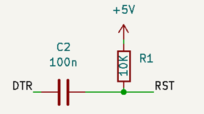
RST -> pin 26 = PF6
RXI -> pin 30 = PA0
TXO -> pin 31 = PA1
In the serial monitor I get a single rectangle character for each time I power the PCB up.
The code is:
void setup() {
  Serial.begin(9600);
  Serial.println(F("Hi"));
}

void loop() {
    Serial.println("in");
    delay (1000);
}
I can live with updating code using the JTAG2UPDI, but cannot debug my code without the serial monitor.
a) Which hardware pins does Optboot use for the serial in each of its versions?
b) What I’m doing wrong?