I am looking for wiring help with an UNO to an IC2 screen with the ChronoDor DS3231 and I don't know where to wire the SCL and SDA wires as the IC2 already is using up the SCL and SDA plugs on the UNO or do I need to redo the wiring completely?
I have a 24V power going into a relay that controls 24V pump that then goes into a step down to be able to power the UNO board with 5V.
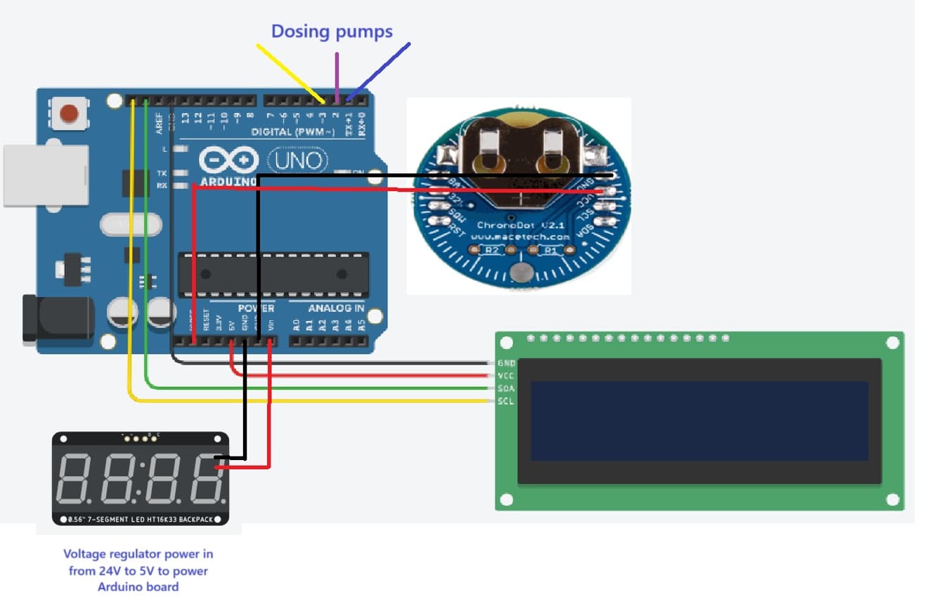
Here is my wiring diagram
I2C is a bus, and as long as all the things you connect to it have different addresses, you can hook them all up to the one set of SCL/SDA pins.
There may be an issue of pull-ups. But the addresses are probably different already, or can be fixed.
Try it, tell us what you see.
If you need to, those pins are also the same as A4 and A5, so you can easily hook a second device up there. A4 is SDA and A5 is SCL.
HTH
a7
This image is from WOKWI?
If so, post your WOKWI project link.
Thanks for the info I will try hooking them up to A4 and A5
No it was a ghetto-fabulous rendition from tinkercad and then windows screen shots as I couldn't find the TRC in the tinkercad library
Why not? Sorry I am brand new to this. Would it be better to move the three relay wires to 8, 9 and 10 or other ones?
Pins 0 and 1 are used for uploading and for the serial monitor. While with some trouble they can be used otherwise, knocking out the potential for using the serial monitor is not worth it.
You have plenty of pins ATM, so just don't use 0 and 1 youself.
Now tell us how the relays are to be controlled by the Arduino. Pins have limited current, so usually using relays involves some kind of module or hand-built driver circuitry, nothing too hard to do.
You might also consider using MOSFET switches which over time will be more reliable than relays, need I add especially cheap relays.
See
a7
Great thanks for the clarification!