Nema 8/17 Stepper Motor Weak Spinning Torque

I'm attempting to run a Nema 8 stepper motor with a Gearshaft, via an A4988 Pololu stepper motor driver, on an Arduino Uno R3.

Datasheets:

I connected the motor and the driver to my Arduino using the simple stepper motor setup, according to the following standard configuration, which I normally use for all my stepper motors:

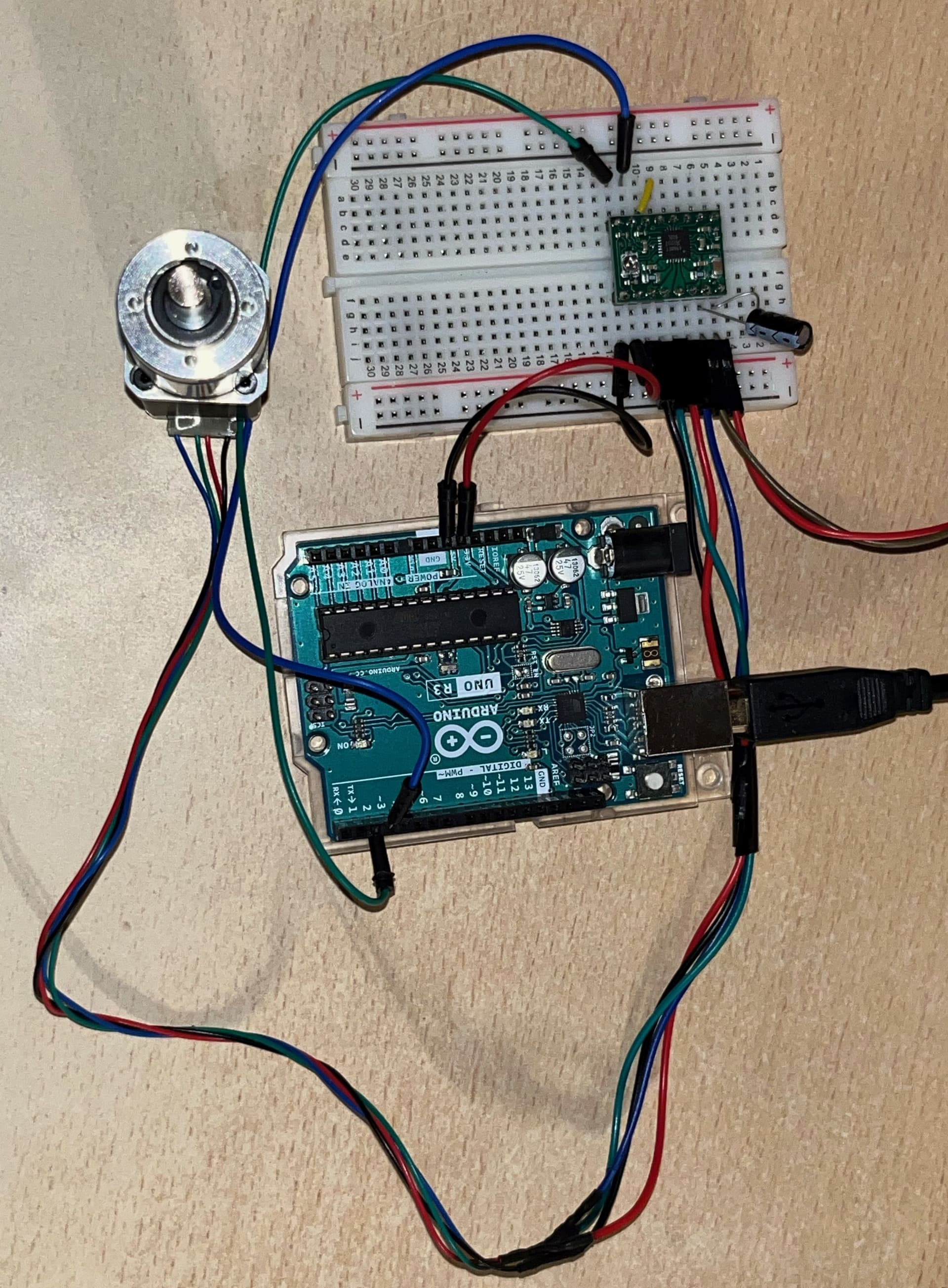
Here is an image of my specific setup:

I'm applying 15V via my DC power supply to the VMOT pins on the A4988 motor driver, alongside a 100 uF capacitor between the two VMOT pins.

I'm running it with the following code on the Arduino IDE:

const int dirPin = 2;
const int stepPin = 3;
const int stepNum = 400;
const int stepDelay = 800;

void setup() {
  Serial.begin(9600);

  pinMode(dirPin, OUTPUT);
  pinMode(stepPin, OUTPUT);
}

void loop() {
  digitalWrite(dirPin, HIGH);

  Serial.println("Spinning!");

  for (int i = 0; i < stepNum; i++)
  {
    digitalWrite(stepPin, HIGH);
    delayMicroseconds(stepDelay);
    digitalWrite(stepPin, LOW);
    delayMicroseconds(stepDelay);
  }

  delay(1000);
}

The setup above allows me to spin my Nema 8 motor with the intended spin direction and duration. However, I'm running into an issue where the torque exerted by the motor while it's stepping is very weak. It's so weak I'm able to halt and slip the shaft of the motor with my fingers, and it's even stranger due to the fact that the holding torque of the motor (torque exterted while it's not stepping) is very strong. I'm not able to dislodge the shaft with my fingers while the motor is holding. Therefore, it is only the stepping torque that appears to be affacted by this weakness...

I have never encountered this issue before, but I've only worked with Nema 17 stepper motors up to now. I have never had a motor exert this strong of a holding torque, and this weak of a stepping torque at the same time.

My first thought was to try out all possible stepping delay durations, and see whether there was a tight sweet spot where the strong stepping torque would step in. I devised a test where I would incrementally increase the stepping delay every few spins in a loop, and found that the torque appeared to be the strongest in the area between 800 and 900 microseconds of stepping delay. Albeit, the torque was still not strong enough to not be stopped or slipped by my fingers.

My next thought was to try and microstep the motor, using the 3 "MS" pins on the A4988 driver. What I found there was even more interesting, where the Quarter Step and Eighth Step actually menaged to extert a lot more torque compared to the Full Step configuration, almost being able to slip through my fingers. It was still not strong enough as I need it to be though unfortunately.

At this point I'm out of ideas.
What am I doing wrong here? Am I missing a certain part of the setup that geared stepper motors, such as this Nema 8, require in order to exert their full torque force?

Thanks for reading my post, any guidance is appreciated.

Breadboard can't carry the current. You need better interconnects for the motor driver and power.

you wrote nothing about that you adjusted current maximum on the driver.
do you determine coils before connecting?
and you can increase voltage on motor.
if 1 wire is not connected(or bad continuity) motor spins chaotically and weak.

Have you set the current limit on the motor driver appropriately? If not, Pololu has a video showing how.

What power supply are you using for the motor? Should be at least 12V, 2A.

Thank you for your reply;

You're right, I didn't consider the current limiting to be an issue here originally.
As far as I understood, I would only have to implement current limiting if I'm supplying a voltage that's higher than the voltage range that the motor I'm running is designed to be ran at. I should have checked the current limitng regardless.

I followed the exact steps of this tutorial, and I set the Vref voltage by turning the current limit screw on my A4988 driver with a scredriwer, and watching the voltage across that screw and a GND on my multimeter.
As far as I understand, I need to know the sensing resistance of my A4988 driver chip in order to plug that value into the equation in order to determine my required value for Vref. The equation as far as I understand is Vref = Imot * 8 * Rsen. According to the tutorial and the Pololu datasheet on the A4988 driver, the sensing resistance can be located on a pair of resistors on the chip.

Here is an image of my specific A4988 driver:

It's a bit hard to tell, but I'm pretty sure that those small resistors say R068, which I understand stands for 0.068 Ohms of resistance.

According to the datasheet of the motor I'm using, the rated current is 0.6A. Since I'm supplying 15V with my DC power supply to the motor, I wanted to try and see whether I can supply more current to my motor, and see whether that improves the situation. I wanted to try and apply 2A of current, which means that, according to the equation above, I'd need to set the value of Vref to 1.088V. I went ahead and did that according to the tutorial, and tried to power the motor. This time the current supplied by my power supply would be significantly higher, sticking around 1.7A - 1.8A during the motor stepping.

However, as positive as this looked, the motor was still unfortunately not strong enough to surpass my fingers.

I also unfortunately am not able to change the supplied voltage, it would have to stay at 15V. That voltage is within the accepted range of voltage for that motor, so it's quite a bit puzzling to me as to why that would not work as intended.

In conclusion, it appears that the current limiting via the little screw did not affect the strength of the motor. Any further ideas?

Thanks again for replying, I really appreciate any help I can get.

Thank you for your reply;

I have just tried setting the current limit so it supplies 2A of current, I supplied all the details in my reply to @kolaha.

I'm supplying 15V with my power supply with a maximum of 5A current, I added that to my original post right after I posted it after I noticed I forgot to include it.

Thank you for your reply;

Upon reading your reply, I went ahead and connected the motor, driver and Arduino together via some 20 AWG wires (which should be rated to carry up to 3A of current) directly instead of the breadboard. I was hoping that might improve the situation.

Unfortunately, it appears that the current drawn from my power supply stayed around the same... It did not appear to improve the situation.

Thank you for your suggestion however, I'll make sure to completely avoid breadboards for stuff like this in the future.

Thanks for your guidance.

I have just tried setting the current limit so it supplies 2A of current

The A4988 driver can supply only 1 Ampere/winding without additional cooling, otherwise it overheats and shuts down. Since you stated that the motor is rated for 0.6 A maximum, that is the value to set on the driver.

According to Vref = Imot * 8 * Rsen and assuming that the sense resistor is 0.068 Ohms, set Vref to 0.33V.

Thank you for your reply;

I'm curious, why do you say that the Pololu A4988 motor driver can only provide up to 1A of current? On the datasheet I linked in my original post, it's stated that it can provide up to 2A... Perhaps I'm misunderstanding how this works.

I followed your instructions and set my Vref value to 0.33V. That limited my current to around the 0.6A that the motor I'm using is stated to be rated for, however the weak moving torque issue still remains...

At this point I'm quite out of ideas, I guess the next step would be to contact the manufacturer and try to get some information from them. I guess I may have also heavily overestimated the strength of the torque this motor can output.

I'll keep you posted if I find out anything more, thanks for the help guys.

shut power off. disconnect motor. cross black and green wires. in datasheet it must be same coil. if it really is will motor shaft be harder to rotate manually. leave black and green free and cross other two wires, red and blue. try to rotate the shaft, it should be same resistance filling. left them free and try now, if is rotates freely then coils are intact.

That is only with significant external cooling. In practice, people find that 1A is the maximum you can expect and Pololu states that on their product page. Manufacturers tend to exaggerate the specifications.

Please post a clear, close up photo of your project so we can evaluate the complete setup. Are all connections soldered?

If you buy cheaply from noname providers, you might be getting counterfeit items. I recommend Pololo, who guarantee their products and provide excellent engineering advice.

Sorry for the delayed reply, been busy with some stuff.

I unfortunately do not have the complete setup yet, because I need to ensure that the motors work as intended first, and can provide the appropriate torque force. If these drivers are not sufficent to drive the motors at the desired torque, I'm going to need to acquire new ones prior to ordering the circuit boards.

I have also decided to switch over to the more common Nema 17 motor, instead of the Nema 8. I've printed out and press-fitted a handle that I could use to measure how strong of a torque the motors output.

As of now, the connections are not soldered. However, I'm not wiring the motor through the breadboard, instead I directly connected them to the A4988 driver with some 20 AWG wires via the connectors on the wires. For testing purposes I'm running the motor with 24V, with the default current limit. I've increased the step delay value from 800 microseconds to 6000 microseconds.
Here's an image of the current motor setup:


In the setup above, the motor spins as intended, however the torque outputted is not as high as the Nema 17 motor is stated to be able to output. I can halt the printed handle with one of my fingers.
I've also tried setting the current limit to the rated current of the motors I have, 1A, to no percieved changes in torque. I've also tried setting the current to as high as it could be set on the driver, yet that also resulted in no percieved changes. As a matter of fact, setting the current limit very high also results in considerable heat being generated on the driver, to the point where it started smelling like bruning plastic and I shut it off. The only thing that appeared to affect the torque outputted very slightly, was setting the voltage to the upper edge of the A4988's input voltage range (9V - 35V). However, that also resulted in a lot of generated heat on the driver.

I've also tried microstepping the motor, using the MS pins, yet that only appeared to weaken the torque instead of increasing it.

After these trials, I consulted a friend who mentioned something I have not thought of before;

It is my understanding that a 2-phase stepper motor works by sending pulses to each one of the two bipolar coils. These pulses are created by whichever controller is controlling the driver, in my case it's an Arduino-based microcontroller (a Teensy 4.0).

In the code I'm running on the Teensy, the actual pulses (sent via the step pin to the driver) are created by the following lines of code:

for (int i = 0; i < stepNum; i++)
{
  digitalWrite(stepPin, HIGH);
  delayMicroseconds(stepDelay);  // Delay 1
  digitalWrite(stepPin, LOW);
  delayMicroseconds(stepDelay);  // Delay 2
}

Where I alternate the step pin between HIGH and LOW, and the actual step takes place on the transition from HIGH to LOW.

Now, as far as I understand, Delay 1 in the diagram above represents the pulse width, while Delay 2 represents the pulse delay. So far I've only tested running these motors with both of the delays shown above being the same length. However, I was wondering whether the mystery of the low torque lies within the durations of these two delays.

What ratio between these two delay values would be appropriate for running these motors?

Another thing I've thought of was to try and view the actual pulses using an oscilloscope.

I conntected the oscilloscope across one of the two coils of on the driver, while it was running the motor. I wanted to track both the holding and stepping voltages on the coil. The results surprised me.

Here is a GIF of the display on the oscilloscope, as the motor alternated between stepping and holding:
ezgif.com-optimize (1)

The thing that was very interesting to me was the fact that, while the motor is holding, there are pulses visible on the oscilloscope display. I would expect for the voltage across the coil to be stable at a certain value while the motor is holding, and not to alternate. Here is a close-up of the display while the motor is holding:

Why are there pulses that are visible while the motor is holding? Could that be a reason for why the motor is experiencing unusually weak torque?

At this point I'm kind running out of options with this A4988 driver.

I will also order a few of the TMC 2209 BigTreeTech drivers that a friend reccomended, which are also commonly used in devices like 3D printers.
I will report if they improve the situation after testing them out.

Did you solder the header pins to the driver board, as required?

Why are there pulses that are visible while the motor is holding?

That is how the motor driver current limiting feature works. The driver disconnects the power supply from the motor coil when the current limit is activated.

Re:

for (int i = 0; i < stepNum; i++)
{
  digitalWrite(stepPin, HIGH);
  delayMicroseconds(stepDelay);  // Delay 1
  digitalWrite(stepPin, LOW);
  delayMicroseconds(stepDelay);  // Delay 2
}

Delay 1 can be very short, or even left out. The driver initiates the step on the rising edge of the pulse. What is the value of stepDelay?

You might be trying to run the motor way too fast. Try this instead:

for (int i = 0; i < stepNum; i++)
{
  digitalWrite(stepPin, HIGH);
  delayMicroseconds(10);  // Delay 1
  digitalWrite(stepPin, LOW);
  delay(500);  // Delay 2
}

If, with the above, you are not getting the full expected torque from a motor, with the driver set to the full rated winding current, there is something very wrong with your setup. But your post does not contain enough information for me to diagnose the problem.

Please post a hand drawn circuit diagram, with clearly labeled pins and connections, and links to the actual components you are using.

This topic was automatically closed 180 days after the last reply. New replies are no longer allowed.