Neopixel LED communication: displaying incorrect colors?

HI! I have a 24-RGB LED neopixel ring and when I tell it to display all red, it sisplays red and then starts changing colors. the colors are just random, and I tell it to only display red. How do I fix it?

Using: Audrino Uno
Power: 2amp 5v power supply
Library: I tried neopixel's, and I tried FastLED.
Sketch:

#include <Adafruit_NeoPixel.h>
#define PIN 6
Adafruit_NeoPixel strip = Adafruit_NeoPixel(23, PIN, NEO_GRB + NEO_KHZ800);

void setup() {
  // put your setup code here, to run once:
  strip.begin();
  strip.show();
  strip.setBrightness(25);
  strip.setPixelColor(0,0,0,255);
  strip.setPixelColor(1,255,0,0);
  strip.setPixelColor(2,255,0,0);
  strip.setPixelColor(3,255,0,0);
  strip.setPixelColor(4,255,0,0);
  strip.setPixelColor(5,255,0,0);
  strip.setPixelColor(6,255,0,0); 
  strip.setPixelColor(7,255,0,0);
  strip.setPixelColor(8,255,0,0);
  strip.setPixelColor(9,255,0,0);
  strip.setPixelColor(10,255,0,0);
  strip.setPixelColor(11,255,0,0);
  strip.setPixelColor(12,0,0,255);
  strip.setPixelColor(13,255,0,0);
  strip.setPixelColor(14,255,0,0);
  strip.setPixelColor(15,255,0,0);
  strip.setPixelColor(16,255,0,0);
  strip.setPixelColor(17,255,0,0);
  strip.setPixelColor(18,255,0,0);
  strip.setPixelColor(19,255,0,0);
  strip.setPixelColor(20,255,0,0);
  strip.setPixelColor(21,255,0,0);  
  strip.setPixelColor(22,255,0,0);
  strip.setPixelColor(23,255,0,0);

}

void loop() {
  // put your main code here, to run repeatedly:
  strip.show();
  delay(1000);
}

1 Like

A good photo of your wiring, will get responses.
To get help, you must show us your complete sketch. Attach your code using the </> icon on the left side of the posting menu.

AS FOR:
Adafruit_NeoPixel strip = Adafruit_NeoPixel(23, PIN, NEO_GRB + NEO_KHZ800);

I think that OUGHT to for sure be:
Adafruit_NeoPixel strip = Adafruit_NeoPixel(24, PIN, NEO_GRB + NEO_KHZ800);

My project used two 16-pixel rings --
Adafruit_NeoPixel pixels = Adafruit_NeoPixel(32, PIN, NEO_GRB + NEO_KHZ800);
[ 2 * 16 = 32 ]

Commands for neopixels I've done use "pixels" instead of "strip"

pixels.begin();
pixels.show();

pixels.setPixelColor(i, pixels.Color(100,0,0));
// only 3 variables vs. 4 in yours
// strip.setPixelColor(0,0,0,255);
// strip.setPixelColor(1,255,0,0);

I can't see the ground of the Neopixel power supply is being connected to the ground of the Arduino. + what R P says about using 24 not 23.

Three resistors: 1K, 10K and 330R? Its hard to see where their legs go. What are the 1K and 10K for?


Grumpy_Mike:
I can't see the ground of the Neopixel power supply is being connected to the ground of the Arduino. + what R P says about using 24 not 23.

The ground of the power supply is connected to the outlet, and to the ground of the ring itself.
I did 23 because I wanted to see if I got different results. Nope.

PaulRB:
Three resistors: 1K, 10K and 330R? Its hard to see where their legs go. What are the 1K and 10K for?

The other resistors are there to reduce power of signal more. One resistor is the pull down, and the other two are in series to the input signal on the ring.

Do I need the data out connected to ground? That might help...

Repet:
The other resistors are there to reduce power of signal more. One resistor is the pull down, and the other two are in series to the input signal on the ring.

Who said that you're supposed to do that?
There should be one resistor - between your Arduino data out pin and the ring's data in pin (1K or so).

#include <Adafruit_NeoPixel.h>
#ifdef __AVR__
  #include <avr/power.h>
#endif

#define PIN   6
Adafruit_NeoPixel pixels = Adafruit_NeoPixel(24, PIN, NEO_GRB + NEO_KHZ800);
void setup()
{
  pixels.begin(); // This initializes the NeoPixel library.
}
void loop() 
{
  pixels.setPixelColor(0, pixels.Color(100,0,0));
  pixels.show();
  delay(1000);
  pixels.setPixelColor(0, pixels.Color(0,0,0));
  pixels.show();
  delay(1000); 
  pixels.setPixelColor(1, pixels.Color(100,0,0));
  pixels.show();
  delay(1000);
  pixels.setPixelColor(1, pixels.Color(0,0,0));
  pixels.show();
  delay(1000);
  pixels.setPixelColor(2, pixels.Color(100,0,0));
  pixels.show();
  delay(1000);
  pixels.setPixelColor(2, pixels.Color(0,0,0));
  pixels.show();
  delay(1000);  
}

Seemed like a good idea at the time perhaps? :roll_eyes:

Repet:
The ground of the power supply is connected to the outlet, and to the ground of the ring itself.
I did 23 because I wanted to see if I got different results. Nope.

You need to connect the Arduino's ground to the ground if the ring as well. Form that description you have not.
Just one resistor 470R, no pull up or down.

Paul__B:
Seemed like a good idea at the time perhaps? :roll_eyes:

yep. the first few LEDs were always White, and that was supposedly how you fixed it.

and that was supposedly how you fixed it.

Who told you that, it is rubbish.

Grumpy_Mike:
You need to connect the Arduino's ground to the ground if the ring as well. Form that description you have not.
Just one resistor 470R, no pull up or down.

ok, I took out the pull down, but why should I connect GND on the ring to GND on the arduino as well?

You need a return path for electrons to travel.

yes, but GND on the ring is already connected to a ground. why two?

draw a representative wiring diagram to show us the way things now.
.

Repet:
yes, but GND on the ring is already connected to a ground. why two?

Because ground is not common by default you have to make it common.

Why ask for help if you are only going to argue?

Do you think that after 50 years in electronics I make these things up. Just connect the dam wires together.

Thing is, without adequate description (perfectly focussed photograph might suit) we really have no idea at all what he means when he says "GND on the ring is already connected to a ground".

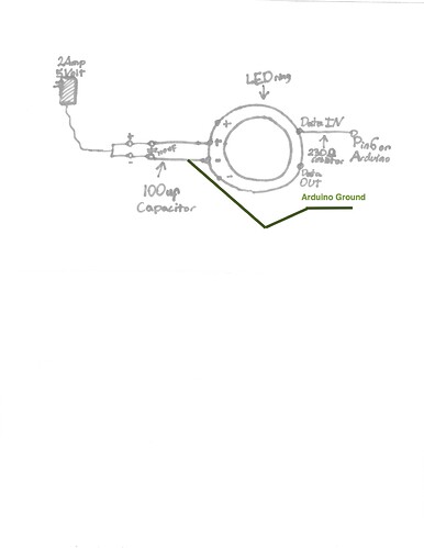
here is a diagram...
Do I need to redraw it?

Wiring Diagram.pdf (140 KB)

Look either connect the ground to the Arduino ground or stop moaning it doesn't work correctly.