Hi all,
I am attempting to get up and running on this board, however I'm have a problem with the basics. Can anybody help me understand why the button example I am pursuing isn't working.
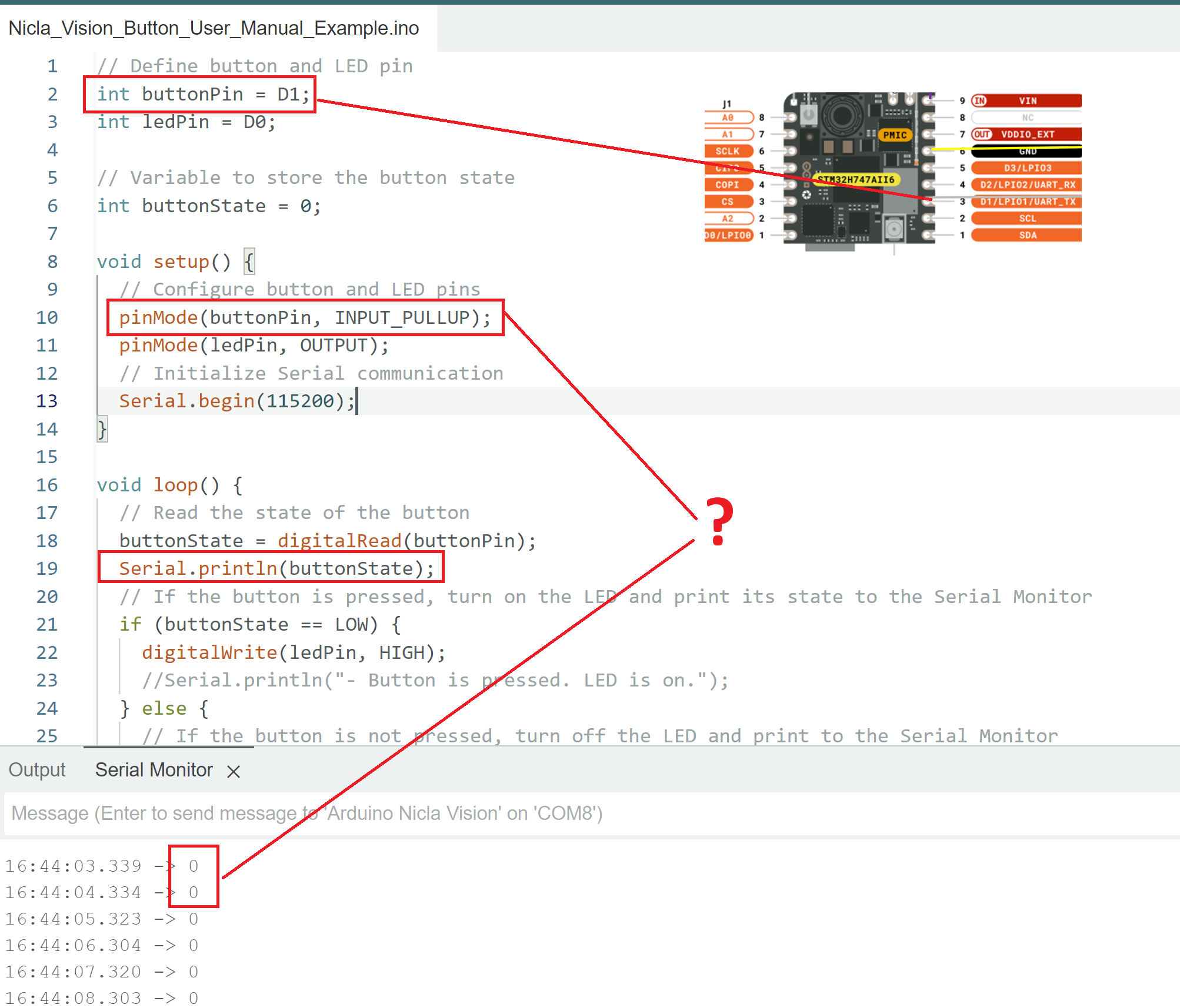
From what I can tell, the board's pullup resistor isn't doing what I need it to. I can get correct behavior by manually connecting the button pin to either ground or high, but upon removing the pin from ground the pull up resistor is failing to set the button high.
I the attached image I am running the code on the Nicla Vision board with nothing attached to it, and it shows that despite enabling the pullup resistor, the pin is reading low. What is going on?
As a second, and I think simpler question... I have successfully completed the flashing LED exercise on the board, but the LED is very dim. Can someone confirm that is to be expected due to the lower power output of the board's I/O pins? That seems to be the case based on the info here which directs that a transistor be used to power the LED rather than the IO digital ports.
// Define button and LED pin
int buttonPin = D1; // Connected to µC PA_9
int ledPin = D0;

// Variable to store the button state
int buttonState = 0;

void setup() {
  // Configure button and LED pins
  pinMode(buttonPin, INPUT_PULLUP);
  digitalWrite(buttonPin, HIGH); //Explictly set the pull up resistor to on.
  pinMode(ledPin, OUTPUT);
  // Initialize Serial communication
  Serial.begin(115200);
}

void loop() {
  // Read the state of the button
  buttonState = digitalRead(buttonPin);
  Serial.println(buttonState);
  // If the button is pressed, turn on the LED and print its state to the Serial Monitor
  if (buttonState == LOW) {
    digitalWrite(ledPin, HIGH);
    //Serial.println("- Button is pressed. LED is on.");
  } else {
    // If the button is not pressed, turn off the LED and print to the Serial Monitor
    digitalWrite(ledPin, LOW);
    //Serial.println("- Button is not pressed. LED is off.");
  }
  // Wait for 1000 milliseconds
  delay(1000);
}
You don't use a resistor if you specify INPUT_PULLUP. However, that is not the cause of your problem. Look for the debounce sample or just Google it; also, there are a hundred libraries. Buttons do NOT go from off to ON, the go off on off on off on off on off on, etc. That's called bouncing. You need to handle that.
It could be that you are connecting to the wrong pins of the push button.
Push buttons with 4 connections can be wired up such that they always appear to be closed.
Use diagonally opposite pins to be assured that the push button is wired correctly.
Thanks JohnLincon. I've tried multiple buttons with the same result unfortunately. I'm going to solder my connections and see if that helps. Right now I don't have very solid connections to the header, and wiggling the connection can restore the high value.
I've also read that there's a way to change the voltage level of the board. I'm wondering if it's operating at an output of 1.8 rather than 3.3, which could explain what I'm seeing. Time allowing I'll put a voltmeter on in and try to make progress. Thanks for the input.
B
Thanks for the suggestion. I am not seeing any debouncing issues. There is a steady stream of reading high or low. I am familiar with debouncing and I get the same behavior with the debounce example. I'm also referring to the internal pull up resistor that's activated by specifying "INPUT_PULLUP". If you've other ideas please do share and thanks again. I'm going to focus on improving the connection via properly soldered connections, which I think could be a factor.
I have never worked with this board, but I see that D1 is also a UART_TX. Find another pin, maybe physical pin 2 which is D18.
You don't need to connect anything to the pin to detect if the pullup is working.
Just read the state of an open pin (declared INPUT_PULLUP) and if it is always HIGH, the resistor is doing its job.
Right now I don't have very solid connections to the header
It sounds like you are not soldering the headers. Good soldering is required for reliable function, and there are lots of tutorials on line that will teach you what good soldering looks like. Breadboards are not reliable, and sticking bare wires into female headers will not work.
If in doubt, check continuity of suspect connections, switches, etc. with your multimeter.