No bass from my Creative Labs I-Trigue 3400 PC speaker system [Solved]

Hi all,

I recently stopped getting any 'bass' output of my Creative Labs I-Trigue 3400 speaker system. I called their tech support, and they said they won't repair it or sell me a new subwoofer speaker part. So I searched online and found and ordered the following the following subwoofer:

So I hooked I connected this new subwoofer when it came the other day, and still no bass. :frowning: I just assumed that that was the problem, but then I realized maybe it's not. (I guess it still could be if all the specs don't match exactly?)

Then since I had the wires of the board free, I pulled it out of the speaker case, and saw that 2 black capacitors looked like part of their outer plastic has melted onto the circuit board:

A closer look:

Maybe this is a stupid question, but would this cause the problem? I just don't get why I get sound out of my 2 'satellite' speakers still though. Is it because those capacitors have nothing to do with the satellite speakers because it's a different part of the circuit or something?

Thanks.

more than likely that's just glue holding them down. are you sure theres not a seperate input for the subwoofer?

Oh. Darn, I was kind of hoping that was the problem. :frowning:

No - the subwoofer is in the same 'box' as the control board is in. However, there is an external volume control device that has a large 'wheel' for the regular volume, and there is a smaller 'wheel' for the bass...

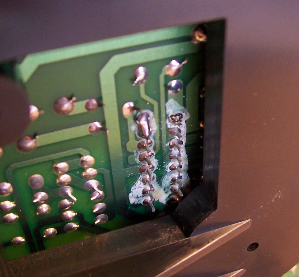
First off - when an electrolytic capacitor dies, it usually blows out the top, where those score marks are (BTW - what's the brand name on the caps? Creative is notorious for using certain cheap brands of caps that die quickly). Even so, does the black goo seem tacky, or stiff? If it was anything from the capacitor, it would likely be a little runny. Also - what does the board smell like (are you aware of what normal PCB versus overheated PCB and parts smell like?). Sometimes that will give a clue.

That part in the back, mounted to the heatsink between the caps - that's a multiwatt15 (package style - same as an L298) audio amplifier of some sort. Can you read any numbers off of it? That would be one good place to start, if you can find a datasheet for it (I may have such a datasheet myself; I have a few such audio amps in a pile of parts I have that I found datasheets for - not saying it will match yours, though). Anyhow, once you had the datasheet, and know which pins are input and which are output, you could then probe with an o-scope (or maybe a small speaker - but a scope would be best) to determine if its getting the signal properly and amplifying it.

It could even be the control box. If you go to the Electro-Tech forums (http://www.electro-tech-online.com/), you might find a thread or two there on similar such Creative speaker system issue being discussed (I've seen them come up before).

Be aware, though, that while you may get good help there, its not as friendly an environment as the Arduino forums; I'm not sure why that is, but I suspect it is populated by more older engineers and such, and less artsy people, coupled with a different mix of international parties than here (it seems the Arduino forums have more Europeans, while Electro-Tech gets more South African, Chinese, and Middle-Easterners, who seem to have less "PC" views of the world - I could be wrong in my views, though). Still, they can be a helpful bunch, if you're patient.

You're probably also going to need to reverse-engineer the schematic on that amplifier board, once you have a datasheet for that amplifier IC. You'll want to start from it, and work your way out from it (drawing the input and output stages before and after than part). Whatever died may have taken out more components that just whatever is initially obvious; its possible the caps died in some manner and took out the amp, or vice-versa. Perhaps other components also died.

Finally - you have to ask yourself if all of this is really worth it; you might learn a lot, but you might end up spending more time and money doing so that you would have had you bought a new system. Only you can decide, though, whether that's a worthwhile tradeoff...

Good luck.

:slight_smile:

Sorry for the belated reply - I was a little overwhelmed (but grateful) by the reply of cr0sh. :wink:

The brand of the caps are 'Jun Fu'. And the black stuff doesn't seem sticky. And I don't know what the board really smells like - I don't have enough experience to know if it smells bad are correct.

Yeah, I can read the numbers on that part against the back against the heatsink:
TDA7378
88014443
V6 88 SGP

A quick search at Digikey shows me that they don't carry it anymore it looks like:

:frowning:

It doesn't seem like it would be hard to just replace it...I don't have an oscilloscope. :frowning:

Here's a picture of the bottom side of the board where all of it's pins are soldered - it looks suspicious - like corrosion or something? Would that be the problem then?

Thank you for all your help cr0sh.

ooh, that definitely looks bad. try resoldering those connections and brushing the corrosion away

What's the best way to clean the corrosion without damaging the circuit board?

Jun Fu is definitely one of the "bad cap plague" manufacturers:

You can find a datasheet for the TDA7378 here:

I would start by cleaning that residue off with some 91-95% rubbing alcohol and q-tips; make sure you remove any stray cotton fibers that get stuck to the pins. If the rubbing alcohol doesn't work, you can try some contact cleaner or similar (buy it at a place like Fry's Electronics - or some other large electronics store that stocks such chemicals). If that doesn't work - last resort might be some goof-off cleaner (well, actually last result would be some diluted pool acid, but that shouldn't really be done).

Once you have it clean, check the solder joints on the TDA7378 carefully, using a hand-held microscope if you have one (if you don't - get one - they are very useful for this kind of work, especially if you build your own boards). A powerful magnifying glass can also work. Jeweler's loupes are also handy to use.

Go over the board, and note the manufacturers on each of the caps, and compare them to the list of "bad cap" manufacturers found at that link above. Do a few google searches as well. Note the ones which are "bad caps", and their values. Make a list of all of them, then purchase new caps (of a manufacturer not on the list, of course). Then go thru, remove each cap and replace it with a new one. You may even have to replace the TDA7378, if you can find a replacement component or a drop-in replacement.

Unfortunately, that's the limit of what I know to do; if you have a scope and a signal generator, you could feed in signals into the TDA7378 and verify operation on the output side. The issue is that if those caps went, there might have been damage to other components along the line; you really need a schematic to be able to follow where and what could be the problem. You might end up spending more money and time on a system that isn't worth it in the end...

Wow, thank you again for all that info cr0sh. I appreciate it.

Hopefully you (or anyone else) won't be mad at me, but before I looked for contact cleaner at Fry's, I realized something. I have the same exact speaker system at work, so just for kicks I decided to bring home the volume control device for it:

As you can see in the picture the volume knob for the bass is circled. I remember that just before my 'sub went out', I was adjusting this little 'bass' volume knob and as I was adjusting it the bass went in and out, then finally never came back on again. I ass-u-me-d that it was just the subwoofer going out. But apparently I was wrong: As I mentioned, I brought home the volume control from work and plugged it into my system here at home, and guess what? Yeah, the bass works.

So I opened it up just to take a look, and took some more photos:


The little thing circled is the LED power indicator. That actually went out on me shortly after I bought it and always wanted to replace it, but didn't know how to find an LED that would directly replace it...but this isn't as big of a deal of course.


Sorry for the blurry picture

So I don't really see anything wrong, so does that mean that the vr1 went bad on me? I'm a little concerned about being able to find another one just like it, especially not knowing any of it's specs. I suppose I could desolder it and see if there are any markings on it like a part number or something, but I'm not sure what to do at this point really.

you could try a 10k potentiometer and see if that works just to test it. im sure you can find an exact replacement on digikey or mouser, but i would test it with a cheap one first to make sure everything is ok. just desolder that black potentiometer and wire another one up the same. left on left side, right on right side, middle on middle. left and right can be switched, the only thing that changes is which way is louder and which way is quieter.

weirdo557,

I happened to have a 10k potentiometer, so I desoldered the existing one, and soldered my 10k potentiometer 'temporarily', and I've got bass! Thank you!

So now I guess I'm going to be on the hunt for the exact replacement!

Thank you everyone thus so far, and I will post back if and when I find the replacement part with a link to it. :slight_smile:

Resolved! Hi everyone. I just wanted to let you know that I eventually found a really close replacement potentiometer from Mouser:

http://www.mouser.com/ProductDetail/Alpha-Taiwan/RV121F-30-009J-A54-00K/?qs=sGAEpiMZZMsEGgLEzQVydk%252bQKPxG2ZAj%2FVzMF%2F2yyQU%3D (Mouser Part#311-1202F-50K)

I'm showing a side by side comparison below to show how close of a match it was:


(Old/original/broken one on the left, new one on the right)

So I just had to clip the main 3 pins to make them fit through the PCB holes, which I actually broke my first one, but I ordered 2 of them thankfully. :slight_smile: Anyway, so I soldered it into place, and it worked! I was so pleased. Oh, I obviously had to keep the actual thumbwheel part from the old one, and put it on the new one because the thumbwheels that came with this potentiometer were not even close, but that's ok. :wink:

Thank you everyone for your help once again, I really appreciate it!

I have one similar to thos system and the remote was cut and removed so i just has the wires. Can you send a good ohoto of the pcb of the remote from top and bottom please so i try to figure out the functions of the wires?

Thanks

This topic was automatically closed 120 days after the last reply. New replies are no longer allowed.