No Wifi connect with ESP32-C3 super mini

I can't manage a Wifi connect with ESP32-C3 Super Mini. The board itself works as far as I can tell (i.e. addressing an OLED via I2C and ssd1306 lib) and it should be able to handle Wifi. Here is my stripped code:

#include <WiFi.h>
char ssid[] = “xxxx”; // my network SSID (name)
char pass[] = “xxxx”; // my network password
WiFiClient client;

void setup() {
  Serial.begin(9600);
  delay(1000);
  Serial.println(“Attempting to connect to WPA network...”);

  int status = WiFi.begin(ssid, pass);
  if ( status != WL_CONNECTED) {
    Serial.print("Couldn't get a wifi connection: ”);
    Serial.println(status, DEC);
    while(true);
  }
}

void loop() {}

In the Serial Monitor this appears:

Attempting to connect to WPA network...
Couldn't get a wifi connection: 6

6 means WL_DISCONNECTED
What am I doing wrong? I am using IDE 2.3.3 on Windows 11.

Not waiting long enough for the WiFi to connect?

Try replacing the above code with the following code

  while (WiFi.status() != WL_CONNECTED) 
  {
    Serial.println("Trying to connect");
    delay(500);
  }
  Serial.println("Connected");

I did with this result: "Trying to connect" forever

I assume you replaced the "xxxx"s with your real ssid / password.
I don't know what the problem could be. I use ESP32 Dev Kit C V4 (WROOM-32D). I've never had a problem connecting to WiFi, but it does sometimes take up to 10 seconds. I can't remember what authentication protocol my router uses.

Correct, I was using real ssid/pwd. Is there an api request if radio is working at all? Or with wrong base frequencies? I haven'f found.

It doesn't support 5.0GHz, so be sure to connect to a 2.4GHz WiFi.

My AP is a 50cm away and supports both 2.4 and 5.0GHz.
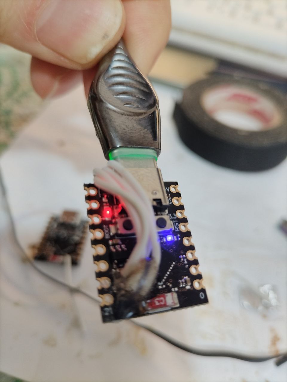
I had doubts if Wifi really works on that module, so I tested it in VS Code with ESP-IDF extension and built a wlan station application. It works, he're the terminal output (I edited secrets to xxxxxx):

....
I (471) phy_init: phy_version 1180,01f2a49,Jun  4 2024,16:34:25
I (521) wifi:mode : sta (48:ca:43:da:e3:cc)
I (521) wifi:enable tsf
I (521) wifi station: wifi_init_sta finished.
I (681) wifi:new:<1,0>, old:<1,0>, ap:<255,255>, sta:<1,0>, prof:1, snd_ch_cfg:0x0
I (681) wifi:state: init -> auth (0xb0)
I (1681) wifi:state: auth -> init (0x200)
I (1681) wifi:new:<1,0>, old:<1,0>, ap:<255,255>, sta:<1,0>, prof:1, snd_ch_cfg:0x0
I (1681) wifi station: retry to connect to the AP
I (1681) wifi station: connect to the AP fail
I (1731) wifi:new:<11,0>, old:<1,0>, ap:<255,255>, sta:<11,0>, prof:1, snd_ch_cfg:0x0
I (1731) wifi:state: init -> auth (0xb0)
I (1741) wifi:state: auth -> init (0x8a0)
I (1741) wifi:new:<11,0>, old:<11,0>, ap:<255,255>, sta:<11,0>, prof:1, snd_ch_cfg:0x0
I (1741) wifi station: retry to connect to the AP
I (1751) wifi station: connect to the AP fail
I (4151) wifi station: retry to connect to the AP
I (4151) wifi station: connect to the AP fail
I (4161) wifi:new:<11,0>, old:<11,0>, ap:<255,255>, sta:<11,0>, prof:1, snd_ch_cfg:0x0
I (4161) wifi:state: init -> auth (0xb0)
I (4171) wifi:state: auth -> assoc (0x0)
I (4191) wifi:state: assoc -> run (0x10)
I (4251) wifi:connected with xxxxx, aid = 1, channel 11, BW20, bssid = 44:4e:6d:3f:e2:ca
I (4251) wifi:security: WPA2-PSK, phy: bgn, rssi: -54
I (4261) wifi:pm start, type: 1
I (4261) wifi:dp: 1, bi: 102400, li: 3, scale listen interval from 307200 us to 307200 us
I (4271) wifi:set rx beacon pti, rx_bcn_pti: 0, bcn_timeout: 25000, mt_pti: 0, mt_time: 10000
I (4301) wifi:AP's beacon interval = 102400 us, DTIM period = 1
I (4311) wifi:<ba-add>idx:0 (ifx:0, 44:4e:6d:3f:e2:ca), tid:6, ssn:2, winSize:64
I (5781) esp_netif_handlers: sta ip: 192.168.3.140, mask: 255.255.255.0, gw: 192.168.3.1
I (5781) wifi station: got ip:192.168.3.140
I (5781) wifi station: connected to ap SSID:xxxxxx password:xxxxxx
I (5791) main_task: Returned from app_main()

Update: I tried another Arduino IDE example "WifiScan". This one works, it shows me available networks.

Scan start
Scan done
5 networks found
Nr | SSID                             | RSSI | CH | Encryption
 1 | xxxx                      |  -38 | 11 | WPA2
 2 | xxxx                     |  -48 | 11 | WPA2
 3 | xxxx                      |  -74 |  1 | WPA2
 4 | xxxx                     |  -77 |  1 | WPA2
 5 | xxxx                     |  -91 |  1 | WPA2

I tried example "WifiClientConnect" - this one fails too.

[WiFi] WiFi is disconnected
[WiFi] SSID not found

It looks like WiFi.begin(ssid, pass); fails for whatever reason here.

I'm trying to turn off Wi-Fi, so I can make pin5 available as an ADC input. There is very little documentation on ESP32-C3 SuperMini, however more people are starting to use them because of size and price. Apparently A0-A4 are free to use but A5 will not work as ADC with Wi-Fi enable.

I added, but it makes no difference:
#include <WiFi.h>
WiFi.disconnect(true);
WiFi.mode(WIFI_OFF);

using a ESP32-C3-MINI-1 the example File>Examples>WiFi>SimpleWiFiServer connects to my WiFi OK
serial monitor displays

Connecting to XXXXXXX
..........
WiFi connected.
IP address: 
192.168.1.65
New Client.
GET / HTTP/1.1
Host: 192.168.1.65
User-Agent: Mozilla/5.0 (Windows NT 10.0; Win64; x64; rv:132.0) Gecko/20100101 Firefox/132.0
Accept: text/html,application/xhtml+xml,application/xml;q=0.9,*/*;q=0.8
Accept-Language: en-GB,en;q=0.5
Accept-Encoding: gzip, deflate
DNT: 1
Sec-GPC: 1
Connection: keep-alive
Upgrade-Insecure-Requests: 1
Priority: u=0, i

Client Disconnected.

a web client displays

document Espressif ESP32C3 ADC states
Since the ADC2 module is also used by the Wi-Fi, reading operation of adc2_get_raw() may fail between esp_wifi_start() and esp_wifi_stop(). Use the return code to see whether the reading is successful.

1 Like

The Sketch I'm doing is for a 21-band Audio Spectrum Analyzer for which I need A0-A2 for audio in, and A3-A5 ADC for Trim pots such as brightness, sensitivity and peak-hold. It works fine on ESP32D which has more pins than I need, and even the Arduino NANO, which only has 32k RAM. I'm using this ESP32-C3 SuperMini 16pin since it has more RAM for the many RGB patterns to the 420 LEDs. I kinda need ADC2 to be made available, but I'm seeing this message in Serial Monitor even with Wi-Fi turned off (supposably).

E (849051) adc_oneshot: adc_oneshot_new_unit(87): adc unit not supported

The first version of ESP32-C3 super mini has a broken antenna design. The workaround is after WiFi.begin reducing the Tx-Power to reduce reflections.

	WiFi.begin(ssid, password);
	WiFi.setTxPower(WIFI_POWER_8_5dBm);

Then I saw in
http://esp32.io/viewtopic.php?f=19&t=42069
the pin 21 issue.
I soldered out the single row male pin 21 and removed

	WiFi.setTxPower(WIFI_POWER_8_5dBm);

again and it connected every time.

2 Likes

Bro, reducing the Tx-Power really helped me. Thanks

1 Like

Thank you, the_merc!
A bad Super-Mini was the root cause, this describes exactly what's wrong:
Super-Mini-Flaw
Two countermeasures helped:

  • Remove the C3 from breadboard, to be precise: remove Pin21, the one which is close by the xtal.

OR

  • Reduce Tx-power

Now it works.

1 Like

Warning: the shop at aliexpress TENSTAR ROBOT Store as described in
esp32-c3-super-mini-flaw
send me 8 weeks ago 10 esp32-c3 of the broken ones. But they were very cheap for 10pcs 13€ :grimacing:
So I now ordered again 2 (Tenstar store) + 2 (Win win store) from aliexpress. More next week.

The now ordered from Tenstar store and Win win store esp32-c3 super mini are the new ones with the working antenna both labeled as TENSTAR ROBOT. The bad one is a former ordered one from Tenstar.


1 Like

If you're okay with lower sample frequencies on the trim pots (say 100Hz instead of 100kHz), you might consider an external I²C ADC like the ADS1115. The breakout from Adafruit is a bit pricy at $15, but unless you really need the QUIIC connectors, similar models are available from Aliexpress for $2 or less.

Greetings to everyone from Siberia, near Lake Baikal.

To address the issue that has been widely discussed here, several steps need to be taken.

1- Desolder the 40 MHz generator (see photo #1).


2- Solder it to the wires and move it as far away from the antenna as possible.
3- The generator has a metal housing that needs to be grounded to the negative terminal. If this is not done, the board will fail to connect via USB.

I soldered the housing to the negative terminal using a soldering iron (see photo). As a result, the board now has excellent Wi-Fi reception, functions well as an access point, and there are no USB connection issues.

Good luck with your experiments!

1 Like

I tried foxsto2025's solution but found that my iron is too big to remove the oscillator. What did work for me was simply moving the antenna (the red component with 'C3' on it) further away! I desoldered it and added two thin (30AWG) wires and soldered the antenna to those. Looks a little funky but it works like a charm now. Good luck all.