I have a NodeMCU project (8266 variety) for Apple HomeKit that allows me to control 4 relays with manual switches, Siri voice control, and the Apple Home app manually via my iPad and iPhone. This all works great and I can turn things on and off using HomeKit.
The project box is powered by a FULARR MP1584EN DC to DC Buck Converter (4.5-28V In to 0.8-20V Out Step-Down Voltage Regulator) that supplies regulated 5V power to the NodeMCU and the relays (and a few status LEDs). This all runs off a 12V DC nominal solar/LiFePO4 battery system in my off grid cabin.
But, set up and coding the NodeMCU becomes an issue after I solder all the components together as the project has two power input sources; the buck converter attached to VIN and the USB micro port. When I want to update code I need to disconnect the project box from the 12V DC power source and power the whole thing via the USB micro port so I can use the Arduino IDE and watch the serial terminal.
What I want to do is build a USB cable that doesn’t supply power at all from my laptop, but simply provides serial communications, which would allow the project box to be powered via the VIN port but still allow me to program and monitor the terminal output using the USB port. I believe it’s risky (or flat-out dangerous) to have NodeMCU connected to power using the VIN pin and USB port simultaneously, even if there is a diode intended to prevent power feedback.
I’ve searched the internet for feedback on if the “no power” USB cable would work, and as usual, find answers that say “sure, it will work fine” and “no way that will work”. I’ve looked at the schematics for the NodeMCU ( HiLetgo ESP8266 NodeMCU CP2102 ESP-12E Dev Board) and it seems like it would work, but I’m no schematic wiz so I thought I’d ask for feedback here.
As I said in the original posting this question (more or less) has been discussed on other NodeMCU sites, with conflicting answers.
Apparently on some NodeMCU boards there is a diode in the design that is supposed to prevent power feeding back from the VIN pin back thru to the USB port and then back into the attached PC (or in my case MacBook Pro). The VIN pin is listed as having a voltage input in the range of 5-12vdc, so I’m thinking that the diode may have issues dealing with voltages in the higher range. But, I don’t want to take a chance and damage my MacBook. So, I’m trying to completely avoid any NodeMCU board differences and simply make a “powerless” USB cable that avoids the issue entirely and still allows me to upload code and watch the serial monitor, with the board powered via the VIN pin (at 5vdc).
So, rather than asking “why do I believe that” do you have feedback on my actual question? Not offended by your question at all, just want to get feedback on what I’m actually asking. Hope that makes sense…
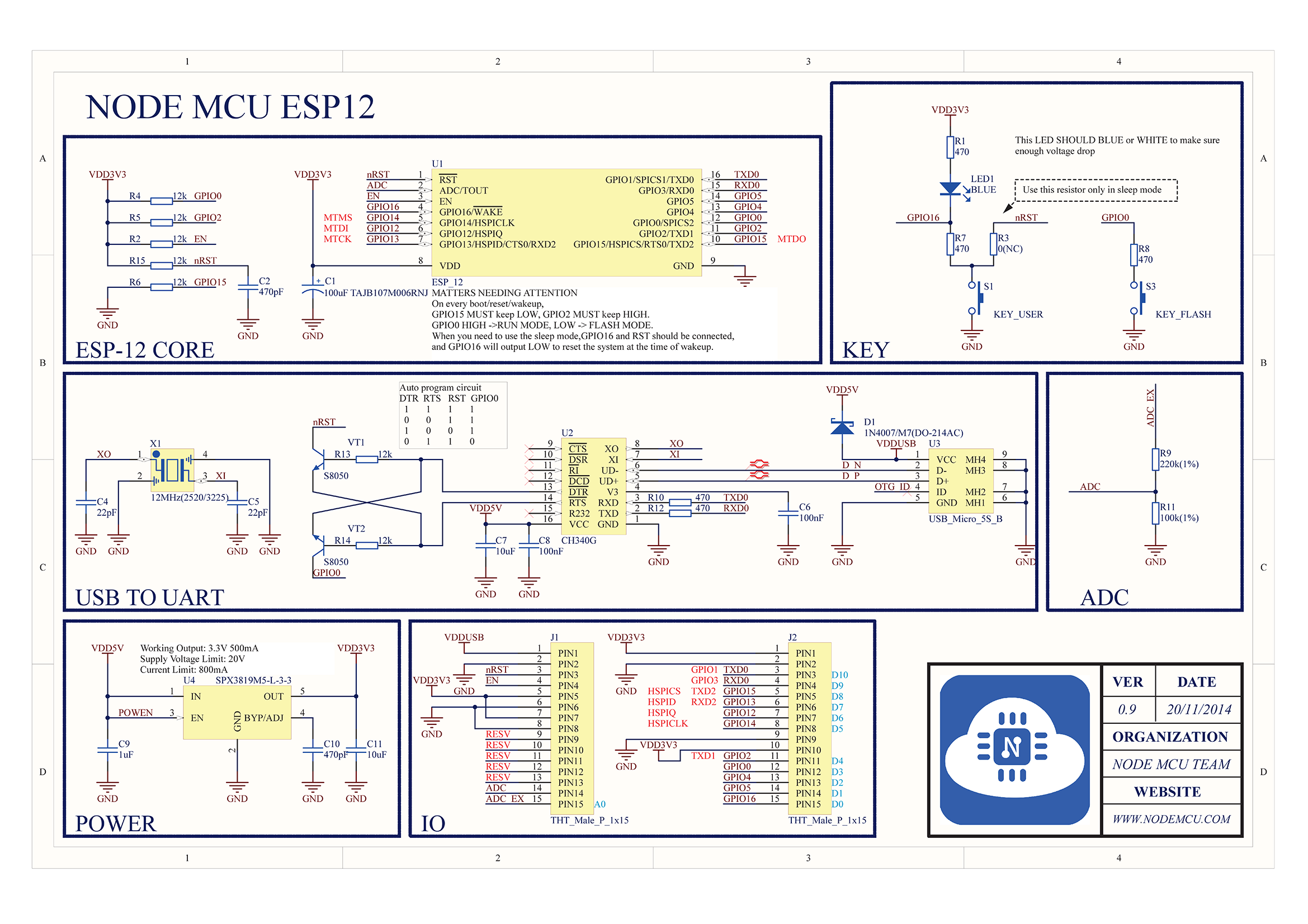
Well, all versions contain the diode but it would appear to depend on whether it is the version 0.9 as illustrated above, where what you refer to as "Vin" - the pin nearest the reset button - is indeed wrongly connected directly to "VDDUSB" and the diode has no function; or the version 1.0 where it connects to "VDD5V" on the "safe" side of the diode.
Or whatever other variant of the NodeMCU you might have. The documentation on the official NodeMCU site is truly woeful and the diagram(s) may possibly be totally wrong.
The obvious first step is to get out your multimeter and test to see whether the diode is between "Vin" and "VDDUSB". Easy enough.
This is also rather important as in the version 0.9, the CH340 is directly connected to "Vin" ("VDD5V") and connecting it to any voltage in excess of 6 V will necessarily "smoke" it. In the version 1.0, the CP2102 connects to "VDDUSB" instead and the diode protects it from higher voltages applied to "Vin".
Yep. I’ve “smoked” one already on a diff project. That’s why I’m asking about making a “special NodeMCU USB cable”. I can easily get USB Micro breakout boards (male and female) and wire them up without the VCC pin connected. Seems like that’s a safe way to go if you’re using VIN to power the board. But will that work? Guess I just need to do it and find out…