Hi guys,
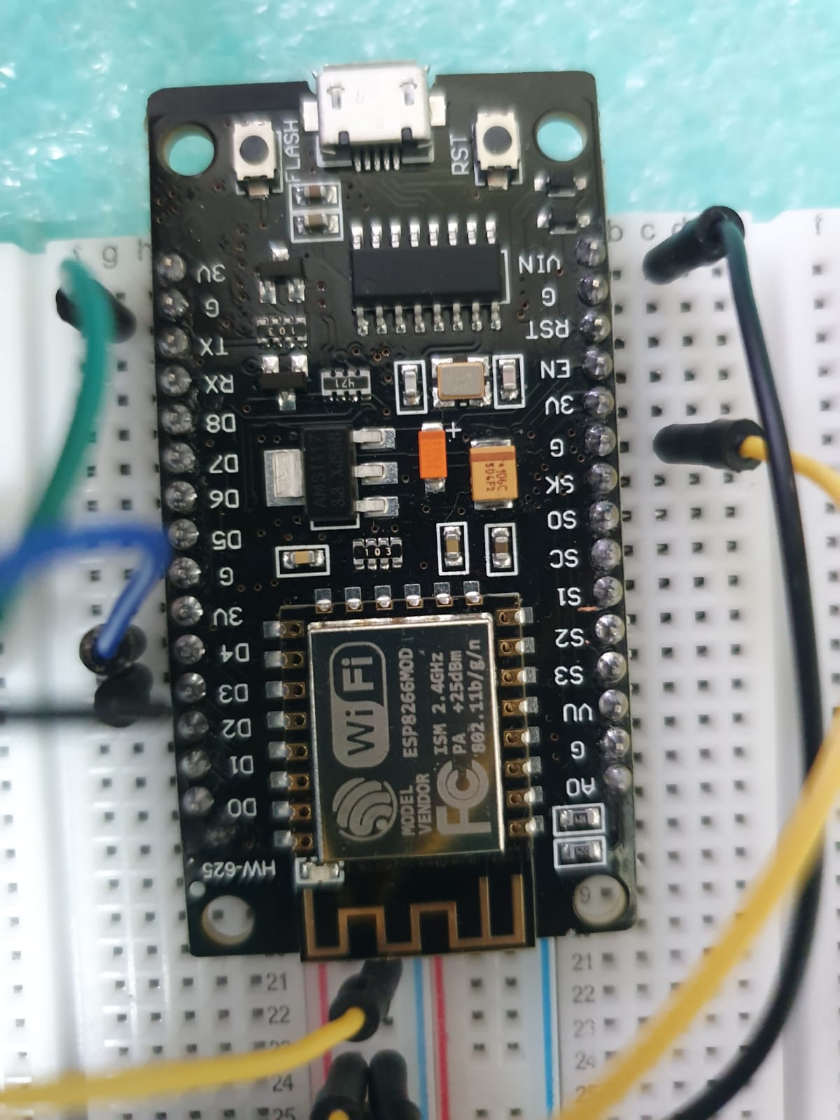
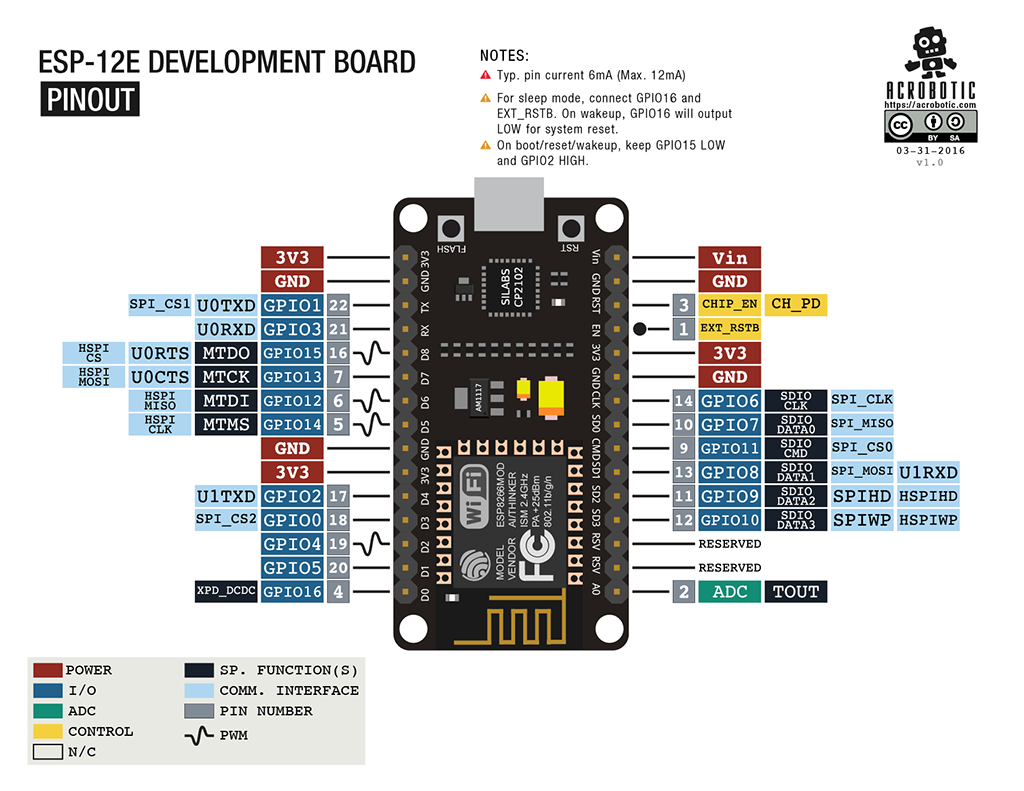
I finally got it working. All I did was changed to Pin 6,7 and in the code changed it to D6, D7. Code seems to be working now. I did not have to use any transistors. I load the code via USB and then unplug and power everything using external power supply. My power supply is set to 5v and feeds relays and the ESP board.
I can trigger relays with voice commands using Alexa. The only item remaining is to add a momentary button to manually trigger relay in case Alexa is on holidays. I have added a momentary button to pin D5 and attached the other side of the button to the ground rail. However, it does not seem to be triggering the relay.
Unfortunately, I have gone over code multiple times without much success. Could someone please give me some pointers?
Thank you for all your help.
// Project for: Alexa Control mains light; + Button
#include <ESP8266WiFi.h>

#define button1_Pin D5

// variables for push button control
byte button1;
byte oldButton1 = 0;
byte button1_state = 0;

#define RELAY_PIN_1 D6
#define RELAY_PIN_2 D7

#include "fauxmoESP.h"

#define SERIAL_BAUDRATE 115200

#define WIFI_SSID "ssid"
#define WIFI_PASS "password"

#define LAMP_1 "Kitchen Light"
#define LAMP_2 "lamp two"

fauxmoESP fauxmo;

// Wi-Fi Connection
void wifiSetup() {
  // Set WIFI module to STA mode
  WiFi.mode(WIFI_STA);

  // Connect
  Serial.printf("[WIFI] Connecting to %s ", WIFI_SSID);
  WiFi.begin(WIFI_SSID, WIFI_PASS);

  // Wait
  while (WiFi.status() != WL_CONNECTED) {
    Serial.print(".");
    delay(100);
  }
  Serial.println();

  // Connected!
  Serial.printf("[WIFI] STATION Mode, SSID: %s, IP address: %s\n", WiFi.SSID().c_str(), WiFi.localIP().toString().c_str());
}

void setup() {


  // Init serial port and clean garbage
  Serial.begin(SERIAL_BAUDRATE);
  Serial.println();

  // Wi-Fi connection
  wifiSetup();

  // LED
  pinMode(RELAY_PIN_1, OUTPUT);
  digitalWrite(RELAY_PIN_1, HIGH);

  pinMode(RELAY_PIN_2, OUTPUT);
  digitalWrite(RELAY_PIN_2, HIGH);

// Manual button
  pinMode (button1_Pin, INPUT);

//***  mySwitch.enableReceive(RF_RECEIVER);  // Receiver on interrupt 0 => that is pin #2

  // By default, fauxmoESP creates it's own webserver on the defined port
  // The TCP port must be 80 for gen3 devices (default is 1901)
  // This has to be done before the call to enable()
  fauxmo.createServer(true); // not needed, this is the default value
  fauxmo.setPort(80); // This is required for gen3 devices

  // You have to call enable(true) once you have a WiFi connection
  // You can enable or disable the library at any moment
  // Disabling it will prevent the devices from being discovered and switched
  fauxmo.enable(true);
  // You can use different ways to invoke alexa to modify the devices state:
  // "Alexa, turn lamp two on"

  // Add virtual devices
  fauxmo.addDevice(LAMP_1);
  fauxmo.addDevice(LAMP_2);

  fauxmo.onSetState([](unsigned char device_id, const char * device_name, bool state, unsigned char value) {
    // Callback when a command from Alexa is received.
    // You can use device_id or device_name to choose the element to perform an action onto (relay, LED,...)
    // State is a boolean (ON/OFF) and value a number from 0 to 255 (if you say "set kitchen light to 50%" you will receive a 128 here).
    // Just remember not to delay too much here, this is a callback, exit as soon as possible.
    // If you have to do something more involved here set a flag and process it in your main loop.

    Serial.printf("[MAIN] Device #%d (%s) state: %s value: %d\n", device_id, device_name, state ? "ON" : "OFF", value);
    if ( (strcmp(device_name, LAMP_1) == 0) ) {
      // this just sets a variable that the main loop() does something about
      Serial.println("RELAY 1 switched by Alexa");
      //digitalWrite(RELAY_PIN_1, !digitalRead(RELAY_PIN_1));
      if (state) {
        digitalWrite(RELAY_PIN_1, LOW);
        Serial.print("LED should be off");
      } else {
        digitalWrite(RELAY_PIN_1, HIGH);
        Serial.print("LED should be on");
      }
    }
    if ( (strcmp(device_name, LAMP_2) == 0) ) {
      // this just sets a variable that the main loop() does something about
      Serial.println("RELAY 2 switched by Alexa");
      if (state) {
        digitalWrite(RELAY_PIN_2, LOW);
      } else {
        digitalWrite(RELAY_PIN_2, HIGH);
      }
    }
  });

}

void loop() {
  // fauxmoESP uses an async TCP server but a sync UDP server
  // Therefore, we have to manually poll for UDP packets
  fauxmo.handle();

  static unsigned long last = millis();
  if (millis() - last > 5000) {
    last = millis();
    Serial.printf("[MAIN] Free heap: %d bytes\n", ESP.getFreeHeap());
  }


// Manually trigger Relay using momentary push button

// Read Button
button1 = digitalRead(button1_Pin);

// Following code is used to switch button state. Input is received from a momentary push button.
if(button1 && !oldButton1) // same as if(button1 == high && oldButton1 == low)
 {
   //we have a new button press
   if(button1_state == 0) // if the state is off, turn it on
   {
     //do stuff
     button1_state = 1;
     digitalWrite(RELAY_PIN_1, LOW);
     Serial.print("LED should be on from Switch");

   }
   else // if the state is on, turn it off
   {
     //do stuff
     button1_state = 0;
        digitalWrite(RELAY_PIN_1, HIGH);
        Serial.print("LED should be off from switch");
   }
   oldButton1 = 1;
 }
 else if(!button1 && oldButton1) // same as if(button == low && oldButton == high)
 {
   // the button was released
   oldButton1 = 0;
 }
}