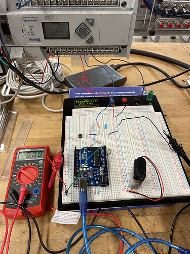
I am new to Arduino coding and I'm having struggles related to analog input with my professor's Robotale Arduino Uno. I am trying to get an analog input from an Allen-Bradley MicroLogix 1400 to the Arduino by hardwiring everything together. However, whenever I use serial monitoring I get floating values all over. To combat this, I used a pushbutton to compensate for this (at least that's a solution I read online to fix that issue). But whenever I press the PB, the serial monitor doesn't receive any value, it just stays at zero, even though the multimeter is reading a voltage of 2.78V.
Show us the code.
Are you trying to charge the 9 volt battery using the power supply?
@FernandoGarcia the code is as follows (I got it from a tutorial):
/*
  ReadAnalogVoltage

  Reads an analog input on pin 0, converts it to voltage, and prints the result to the Serial Monitor.
  Graphical representation is available using Serial Plotter (Tools > Serial Plotter menu).
  Attach the center pin of a potentiometer to pin A0, and the outside pins to +5V and ground.

  This example code is in the public domain.

  https://www.arduino.cc/en/Tutorial/BuiltInExamples/ReadAnalogVoltage
*/

// the setup routine runs once when you press reset:
void setup() {
  // initialize serial communication at 9600 bits per second:
  Serial.begin(9600);
}

// the loop routine runs over and over again forever:
void loop() {
  // read the input on analog pin 0:
  int sensorValue = analogRead(A1);
  // Convert the analog reading (which goes from 0 - 1023) to a voltage (0 - 5V):
  float voltage = sensorValue * (5.0 / 1023.0);
  // print out the value you read:
  //delay(500);
  Serial.println(voltage);
}
@Paul_KD7HB No, the battery is actually there because the rest of the circuit is closed to the outputs of the MicroLogix. The terminal groups need a power source to work, so I have the 9v closing the loop between an output terminal and a coms terminal from the controller.
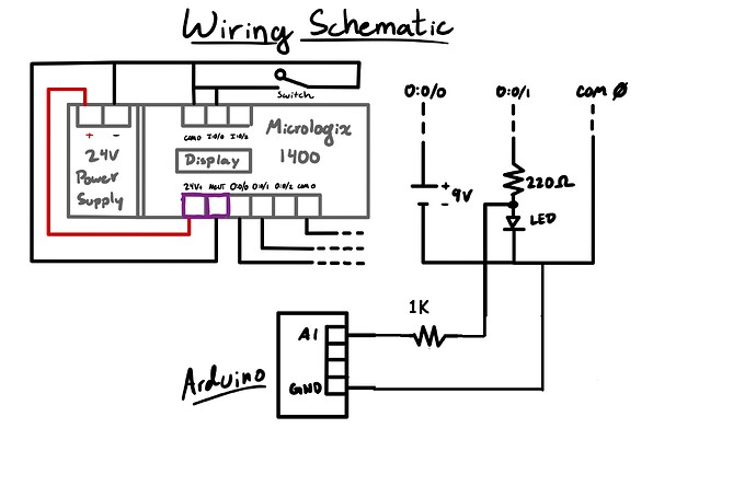
Can you make a schematic by hand of this circuit?
The image is not so easy to understand.
The wiring of this button doesn't look right to me.
I can see:
Analog pin > button > 10 k resistor > GND
So while the button is not pressed the pin is floating.
They mention analog pin A0 but the code mentions analog pin A1? Which analog pin are you using? Because other than that quirk the code is fine for a signal applied to A1. With this simple analog read there should be no need for a button. I am also assuming for example an Arduino Uno or similar with a 5 volt reference.
Ron
@FernandoGarcia sorry for the late reply, but I have this as a schematic (sorry if its not detailed enough). I tried the wiring of the button without the MicroLogix hooked up and it worked properly (I used this video as reference: Short and sweet: pull up/pull down resistors explained - YouTube)
@Ron_Blain sorry about that, yeah I changed it to A1 because as I was troubleshooting, I thought maybe my issue was with the pin itself and was probably worn out or something. After changing it from A0 to A1, I saw the same issue. In regards to the button, if I don't have it, I keep reading random numbers fluctuating in the serial monitor; with the button, I am able to keep it at 0V
Hi, @jorgebarronjr
Welcome to the forum.
Try this, you need a gnd reference when inputting a signal the the UNO.
The 1K is just for safety.
Then you should get a value from the analog input when the LED lights.
If you get varying readings when the LED is OFF.
Put a 10K resistor between the A1 input and gnd.
Tom.. ![]()
![]()
![]()
![]()
Thanks @TomGeorge I'll try this tomorrow, I am out of campus rn so I have to be where the MicroLogix is. I'll give an update on this but I appreciate the advice a lot. Cheers.
For this wiring the input_pullup should be activated on setup, no?
Because when there's no input voltage before the 220r resistor the pin will be floating.
Hence the recommend 10K input to gnd.
Tom.. ![]()
![]()
![]()
![]()
Hey @TomGeorge it worked as how you drew it in the schematic. I really need to dive into electrical wiring more haha. Thanks for your help.
This topic was automatically closed 180 days after the last reply. New replies are no longer allowed.


