HI to all that read this one.
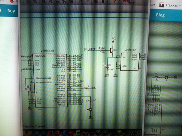
What I would like to know is the correct way to wire (NPN transistor as A switch).
I want the npn to switch the (ADxl335 3 axis accelerometer) on and off.
Right way 1
Right way 2
Or both ways will work.

HI to all that read this one.
What I would like to know is the correct way to wire (NPN transistor as A switch).
I want the npn to switch the (ADxl335 3 axis accelerometer) on and off.
Right way 1
Right way 2
Or both ways will work.
Have you googled Transistor as a Switch?
Both are wrong for your application.
You need a top switch. That is one like diagram 1 but with a pnp transistor and then driving that transistor you need another NPN transistor.
I'm thinking #1 will work because its an emitter-follower circuit and would only have about 0.7V less at the emitter than the control signal at the base. This accelerometer is single-supply operation from 1.8 V to 3.6 V, so it would power up OK. When the control signal is logic HIGH it would turn ON, Logic LOW to turn OFF.
Example 1 would rely on the digital signal (controlling the base) to be able to get at least .6v higher than the requirements of your circuit. This is not necessarily going to happen reliably.
Example 2 would be easier to drive as you only have to get your digital signal higher than 0.6v BUT that would leave the ground of your circuit tied to this 0.6v false ground rail and could lead to some unpredictable results.
If you're going for a single transistor solution then a PNP on the 5v supply would be a better option. This would, however, give you reversed logic. (pulling the base low will turn on your circuit). Driving the base of this PNP low by means of an NPN (as Grumpy_Mike suggested) would be even better. It would also restore your logic to high for on.
Grumpy_Mike:
... and then driving that transistor you need another NPN transistor.
Why?
Paul__B:
Why?
As KenF said, to keep the "on" signal high rather than low. If the OP can use a low signal to turn on the PNP, then the NPN would not be needed.
Emitter Follower
The emitter follower is a very simple current amplifier, taking advantage of the fact that IC = ßIB. The high input impedance means that our imput signal does not need to "work" as hard.
Example:
Transistor: 2N3906 2N2222A
hFe (ᵝ) = 100
VBE(SAT) = 0.65V
Base resistor: 2K
Base drive voltage: 3.3V
Output voltage: 2.6V
Base current = 0.65/2000 = 325µA
Max. collector current = 325µA * 100 = 32.5mA
Load: adxl335
Single-supply operation: 1.8 V to 3.6 V
Low power : 350 µA (typical) = 0.35mA
As it says the emitter follower is an amplifier. That's not a switch.
Normally you'd use common-emitter configuration for switching, so if you want
to have commoned up grounds that forces high-side switching with a PNP or p-channel
device.
Sometimes you can get away with it, but here you have an analog sensor whose output
is ratiometric to the supply, use a p-channel MOSFET high side switch if you want the
output to remain accurate to the specifications. (you'll get sub-miilivolt error doing this).
If you use a BJT switch you could route the post-switching supply to another
analog pin in order to correct for the voltage drop in the transistor (which hopefully
isn't too bad for a low-current load like this, perhaps 0.1V).
If (DC) accuracy isn't important, or if you don't need commoned grounds, there are
more ways to do this.
Paulcet:
As KenF said, to keep the "on" signal high rather than low. If the OP can use a low signal to turn on the PNP, then the NPN would not be needed.
Granted that this is the "General Electronics" discussion area, we would expect that the question is in regard of using an Arduino to perform the control function. ![]()
Yes the Arduino will perform the control function, at 3.3V. There is no sleep pin on the ADXL335, so I want
to use the NPN Transistor (PN2222A) as the sleep pin.
If I did my math right.
Max. collector current = 325µA
B=100
V = 3.3
The Resistor to control the npn will = 2k
AND Thank YOU all for your input's......................
BenBenBen:
Yes the Arduino will perform the control function, at 3.3V. There is no sleep pin on the ADXL335, so I want
to use the NPN Transistor (PN2222A) as the sleep pin.
Yes, except that as almost everyone here has been explaining to you, you need a PNP transistor.
And it would probably be an idea to open the blinds when you take your photos.
Hi, question, why do you want to turn the IC off, it only consumes 350uA?
Tom..... ![]()
I am going to use, 9V battery to run the Arduino. I want the Arduino and ADXL335 to be on for about 3 hours.
Then the rest of the time I want then to go to sleep. The sleep might be for 3 days to 3 weeks.
We don't know your complete circuit, but you may need to "disconnect" the XYZ outputs while in sleep mode. If that's the case, perhaps something like this could effectively shutdown the power and the 3 outputs of the ADXL335. Typical supply current for this quad analog switch is only 0.001µA.
A 9V smoke alarm battery is typically 500 to 600 mAh. An arduino draws 50 mA when it is doing nothing.
That's 10 hours if you are not driving anything. If you add leds or other chips, that 10 hours goes down.
In most applications, you can expect 6 to 8 hours of operation of a circuit with a 9V battery unless you try
something crazy like driving motors.
Just look up "latch up" before you complete your design.
You'll recall that I suggested that you need a PNP as you can't be sure a digital signal will get high enough to turn on an NPN on the positive rail?
Having switched to a PNP you could potentially have the opposite problem. dragging the pnp down low enough to turn it on will be a synch, but turning it off again may not be so reliable.
If you have the base of an NPN on the signal with it's emitter connected to the ground rail, there's no doubt that you'll be able to turn that on and off. Using this to drive the PNP on the positive rail will be absolutely bullet proof. You MAY get away with just using the PNP but the NPN driving it will make it a certainty. (and also maintain the logic of the circuit. Grumpy_Mike's suggestion is definitely the best solution IMHO
KenF:
Having switched to a PNP you could potentially have the opposite problem. dragging the pnp down low enough to turn it on will be a synch, but turning it off again may not be so reliable.
Why not? The Arduino (ATmega328) chip does that perfectly reliably.
raschemmel:
A 9V smoke alarm battery is typically 500 to 600 mAh. An Arduino draws 50 mA when it is doing nothing.
Which raises two points.
One is that you need to use a Pro Mini which does not have the overhead of the USB to TTL chip and you need to carefully remove the resistor which controls its power indicator LED in order to minimise the current draw when you put the ATmega chip to "sleep".
The other is that you should not use a 9V "PP3" battery to run an Arduino combination for any period of time (and that presuming it is "sleeping" almost all of the time), rather use a decent battery pack such as a five-cell "AA" holder.
Even that however, misses another problem. If you put the Arduino to sleep, the major current wastage will actually be through the substantial quiescent current of the regulator. Presuming the sensor can actually tolerate some voltage loss, you might be better to use a four-cell battery to provide 6V and drop a little with a silicon diode to supply the Arduino without the regulator.
Since the consensus here is to stay away from using an NPN connected as an emitter follower to switch power to an IC, I thought I would test the less desirable PN2222A as it's VBESAT is 0.6V. In a 3.3V circuit, I would expect around 2.7V at the emitter.
I used 2.2K in series with the base and another 2.2K connected emitter to GND for a 1.5mA load. I used an Arduino Due PWM output at 1.2kHz and measured a sharp 1.2kHz signal at the emitter, 2.68V peak with about 20ns rise/fall time.
Adapting the adxl335 to use sleep mode may require that other signals be disconnected, but who knows, we don't have the complete circuit.
