hi all,
i'm looking at using an arduino to switch a guitar signal on and off - arduino pin goes high to base of transistor allowing guitar signal to flow - the problem is, if i'm not mistaken, is that transistors have a small voltage drop between the collector and emmitter, and guitar voltages are in the milli volt range already - somewhere between 200mV and 2V depending on pickups etc, but if the voltage drop across the collector and emmiter is 200mv , there may not be much left.
is this correct? can a transistor switch be used to switch such small voltages - the voltage of a guitar signal is its volume so if the voltage drop is too large there is a noticeable volume drop.
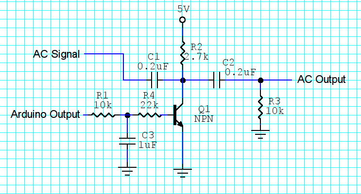
It is possible to control your signal with a bipolar transistor, but it will probably inject "clicks" into your audio signal when you turn it on and off, and it will attenuate your pickup signals even when they are turned "on". The scheme roughly might look like this:
Another better approach though might be to let your Arduino "fade" your signal, rather than turning it on and off abruptly. You can accomplish this with a "digitally controlled potentiometer" like this one.. These chips are available from places like ebay for about $1.00. They're also available in an Arduino-friendly module form.
gaiastellar:
the problem is, if I'm not mistaken, is that transistors have a small voltage drop between the collector and emitter, and guitar voltages are in the milli volt range already - somewhere between 200mV and 2V depending on pickups etc, but if the voltage drop across the collector and emitter is 200mv , there may not be much left.
It sounds as if you are proposing to connect the transistor in series with the signal. This involves a number of problems, mostly to do with providing bias to provide a current flow through the transistor, in which case the voltage drop becomes a constant and the signal is transferred easily.
The point is that bipolar transistors are simply obsolete for this function, replaced by MOSFETs. Further than that, ICs are designed specifically for this purpose, called "analog switches". The one you want is the 74HC4066 or its fellows; they have an "on" resistance of about 60 Ohms which is trivial compared to the impedance of most line-level audio signals - and a very high "off" resistance. You do need to provide DC isolation with capacitors.
gaiastellar:
hi all,
i'm looking at using an arduino to switch a guitar signal on and off - arduino pin goes high to base of transistor allowing guitar signal to flow - the problem is, if i'm not mistaken, is that transistors have a small voltage drop between the collector and emmitter, and guitar voltages are in the milli volt range already - somewhere between 200mV and 2V depending on pickups etc, but if the voltage drop across the collector and emmiter is 200mv , there may not be much left.
Draw the circuit you are proposing, it does sound rather unlikely though, if you want to switch / route
analog signals without using physical switches a CMOS analog switch chip or small relay is the component to chose.
For an ac signal around ground you either need a negative supply to use any analog circuitry
to transmit/process/signal it, or level convert it up to say 2.5V first (bit like posting #3), or just use a physical relay.
MarkT:
For an ac signal around ground you either need a negative supply to use any analog circuitry
to transmit/process/signal it, or level convert it up to say 2.5V first (bit like posting #3), or just use a physical relay.
You may have something in particular in mind here MarkT but I think it would benefit from some clarification. I may be misunderstanding you.
In general, you don't need a negative supply to process AC signals unless the signal spectrum contains important low-frequency components that make the use of capacitive coupling impractical.
In the sketch I provided in my earlier post here, the AC input and AC output in the steady state will both vary around the ground reference. When the transistor is OFF, you can see that you have what amounts to a high-pass filter between the AC Input and AC Output terminals. When the transistor is ON, the junction of C1 and C2 will be at about 0.3V DC -- but at ground potential as far as the AC Input signal is concerned (the transistor is acting like a voltage source in that state).
Over the audio spectrum, you should be able to choose reasonable C1 and C2 values to make the high-pass filter issue unimportant in this application. The big problem though, is that when the transistor switches between its ON and OFF states, the circuit will generate significant transient spikes. That's why I recommended "fading" rather than any simple ON/OFF approach. Audible clicks and pops may accompany ON/OFF switching pretty much regardless of how the switch is implemented, depending on the guitar and the amplifier it's connected to.
CurtCarpenter:
You may have something in particular in mind here MarkT but I think it would benefit from some clarification. I may be misunderstanding you.
In general, you don't need a negative supply to process AC signals unless the signal spectrum contains important low-frequency components that make the use of capacitive coupling impractical.
I used the phrase ''or level convert it up to say 2.5V first"...
allanhurst:
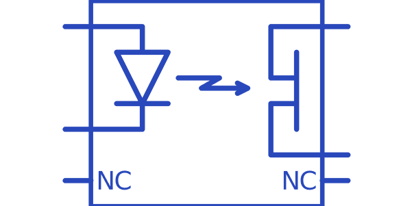
The enclosed works perfectly. No clicks. And no dc problems. I've used it in several products.
It might be worth adding eg 100n across R3 to eliminate switchbounce.
A depletion jfet is completely symmetrical. S and D are interchangeable.
Allan
JFETs are getting rarer and rarer these days though... Most modern equipment routes all analog inputs
to an ADC with built-in multiplexer and does everything else digitally, so there's little need for JFET
switchery and if you do want extra MPXing CMOS analog switches are used - you already have to
level convert (or use differential signalling) for the ADC anyway these days. The advantage being
one analog switch chip can have many many switches in one package with direct logic control inputs.
allanhurst:
If you want much more attenuation ( > 60dB or so) a shunt as well as series device kills it stone dead.
I can believe that.
I put your circuit together here using a PNP transistor (2N3906) to drive the JFET gate and it seems to work well (even without thinking much about sizing resistors in the collector and base). Seems pretty robust.
It might be worth creating that negative rail if it isn't already available, just to get the nice quiet switching and large signal-handling range the JFET seems to provide.
MarkT:
JFETs are getting rarer and rarer these days though... Most modern equipment routes all analog inputs
to an ADC with built-in multiplexer and does everything else digitally, so there's little need for JFET
switchery and if you do want extra MPXing CMOS analog switches are used - you already have to
level convert (or use differential signalling) for the ADC anyway these days. The advantage being
one analog switch chip can have many many switches in one package with direct logic control inputs.
All very true.
But for a single channel with a few 100mV signal which may be switched 'live' the simple JFET works well.
Ages ago I designed a small (5W) talkback amp for TV studios which had limiting/compression AND a 'squelch' circuit. By controlling a jfet gate's rise and fall times for the latter absolutely no audible click was detectable. My successor in that post didn't like the fet ( 'far too old-fashioned'), redesigned it and put in a DG300 analog gate. Definite click. And a lot dearer.
The jfet's 'on' with no power can also come in handy for peculiar jobs - I once had to do some signal processing for a redox gas-sensing cell which required shorting out when not in use. The gubbins was driven by a 4-20mA loop, so I didn't have much spare power to drive a N/C relay.
JFETs have their uses, even now.
Allan
ps CurtCarpenter : if you use a p-channel jfet the logic signal is 'high' for off. They're still about.