I've read numerous tutorials on this matter and I'm getting very confused.
Here's my situation: I have a device I wish to control. It has a handy switching circuit built in and I wish to utilize its switching circuit with an Arduino.
Here's what I know about the device: There are two terminals for the switch. Completing the circuit activates the device. The two terminals have 12V, 2 mA and 0 ohms across them.
I was thinking about using an NPN transistor to utilize this circuit. I'd settled on something like a 2N4401 but I'm not 100% sure on this, because I'm having a lot of confusion about these kinds of NPN switching circuits. Following 3 different tutorials, I've got 3 different values for the resistor that connects to the base.
Here's my setup: Collector to 12V. Base to Arduino pwm out (operating either high or low only for simplicity). Emitter to 0V. Arduino GND and device 0V connected. For the base resistor, I've gotten anything from 100 ohm to 59k ohm.
What's really tripping me up is that the maximum possible output from the Arduino (Ib) could, in theory, exceed the current going to the collector (Ic). Does this matter? What should the Rb be? Have I even selected a sensible NPN transistor for this design?
Apologies, I'm just really trying to learn electronics for the first time and this is likely a very silly question.
I've got 3 different values for the resistor that connects to the base.
The base resistor value is super non critical. 1K is always good for a start.
Base to Arduino pwm out
Why send it PWM, that is going to switch it on an off rapidly? Almost certain not what you need. Anyway it should be arduino output to resistor other end of resistor to base of transistor.
There is a lot of Physics theory you could use to approach this problem... but you are admitting that you are not an Electrical Engineer so you are probably not quite ready for the deep explanations and the theoretic mathematical solutions that an EE explanation would toss at you. So, the next best approach is the Electronics "technician" cookbook approach. Start to learn what works... and apply it.
Based on your explanation here are some thoughts.
The tried and true cookbook solution for a typical low power NPN switching transistor (2N4401, 2N3904, 2N2222 etc), with 5V logic driving the base, is to use a 1K resistor. Is it perfect, maybe not. Does it work pretty much every time? Yes. It will make the typical NPN go from OFF to ON.
What you are describing may not be quite right for using an NPN transistor switch. You would not want to apply 12V to the collector, since it is preferred to use the NPN transistor in a "sink" switch (supply path to ground) configuration. When you are switching HIGH side, a PNP device is preferable. Secondly, your configuration as stated will just create a short between 12V and GND.... (not preferred since that creates magic smoke release from transistor and they stop working without it) If you had a resistor in the path to control current between Collector and Emitter... maybe not so bad.
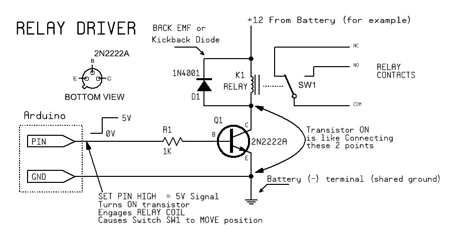
If you look at my drawing... I would recommend using a relay to create the switch closure between the contacts since it's not really clear what those 2 contacts expect... but a relay contact closure will remove the need to know.
Thanks for the reply pwillard. I'm not certain a relay will work in the application I have in mind. I'm looking for timing on the scale of 5 - 10 ms. The fastest reed relays I am (ignorantly) aware of are around 200Hz, which is just barely inside the range I am looking for. It is something I will certainly try and I could think of ways to compensate for the time it takes to activate a relay.
I'm also not 100% on the theory (as should be obvious!) but I think a PNP device will give me the opposite switching action. HIGH applied to the base will turn the circuit off. My goal is HIGH applied to base turns the circuit on.
srose82:
The two terminals have 12V, 2 mA and 0 ohms across them
That combination doesn't make sense. I can believe 12V open circuit and 2mA short circuit, but 0 ohms? How did you measure those values?
srose82:
Here's my setup: Collector to 12V. Base to Arduino pwm out (operating either high or low only for simplicity). Emitter to 0V. Arduino GND and device 0V connected. For the base resistor, I've gotten anything from 100 ohm to 59k ohm.
If by "Collector to 12V" you mean collector to the pin of the device you want to switch that is at +12V in the open circuit condition, then that may work (but use a digital output as already suggested, not a PWM output), depending on whether the other terminal is or can be at ground potential. Can you tell us a little more about the device you want to control?
I thought I'd provide an update: I bit the bullet and built a circuit using the 2N4401 NPN transistor. I wired digital output pin 2 of the Arduino to a 1K ohm resistor and the 1K ohm resistor to the base of the transistor. I wired +12V to the collector and gnd to the emitter. So far so good, I'm controlling the device.
dc42,
I know it doesn't make sense given I=VR. I just measured across the terminals using a multimeter. These control terminals seem to be just a way of completing a pre-existing circuit. In order to utilize the remote control capabilities these terminals provide, you have to remove a piece of metal that is just shorting them together.
I am using this method for switch an LED array. I have 4 Arrays each with its own transistor (TIP 122 NPN) 3 of these arrays are working fine on the forth the LEDs are dim. No matter which array I hook up to this transistor that array is dim. I check the voltage between the collector and the +12 rail and I am only getting +7.24v. I figured maybe the transistor was bad so I swapped it out and am having the same issue. If I unplug the array completely and test the voltage between the Collector and source I get +11.3 v.
So I am wondering where else the problem could be? The only other parts in the circuit are the Nano and the resistor (1k) between the Nano and the transistor Base.
Here is an image of my circuit. Any help would be greatly appreciated.
Check that the 1K base resistor really is 1k and you have not inadvertently used a higher value. Similarly for the 150 ohm resistor in series with the LED.
Check that you have made a call to set the pinMode of the pin driving the TIP122 to OUTPUT.
Check that when the LED is switched on by the TIP122, the TIP122 emitter is at 0V in case you have a bad or missing ground connection..
Thanks for the help.
I have found my problem, but don't know what caused it. For some reason Pin 2 on my Nano is only outputting 1.26 v. I guess somewhere along the line it got damaged. I switched to another Pin for output and my problem is gone, at least the immediate problem with the LED array.
The resistor is a 1k
Pinmode is set to OUTPUT
The emitter is reading 0v
Glad you got it working. It sounds to me that the output driver on that pin has failed and only the internal pullup resistor is working (just as if you hadn't made the pinMode call).