NRF24+ not working

Hello guys,

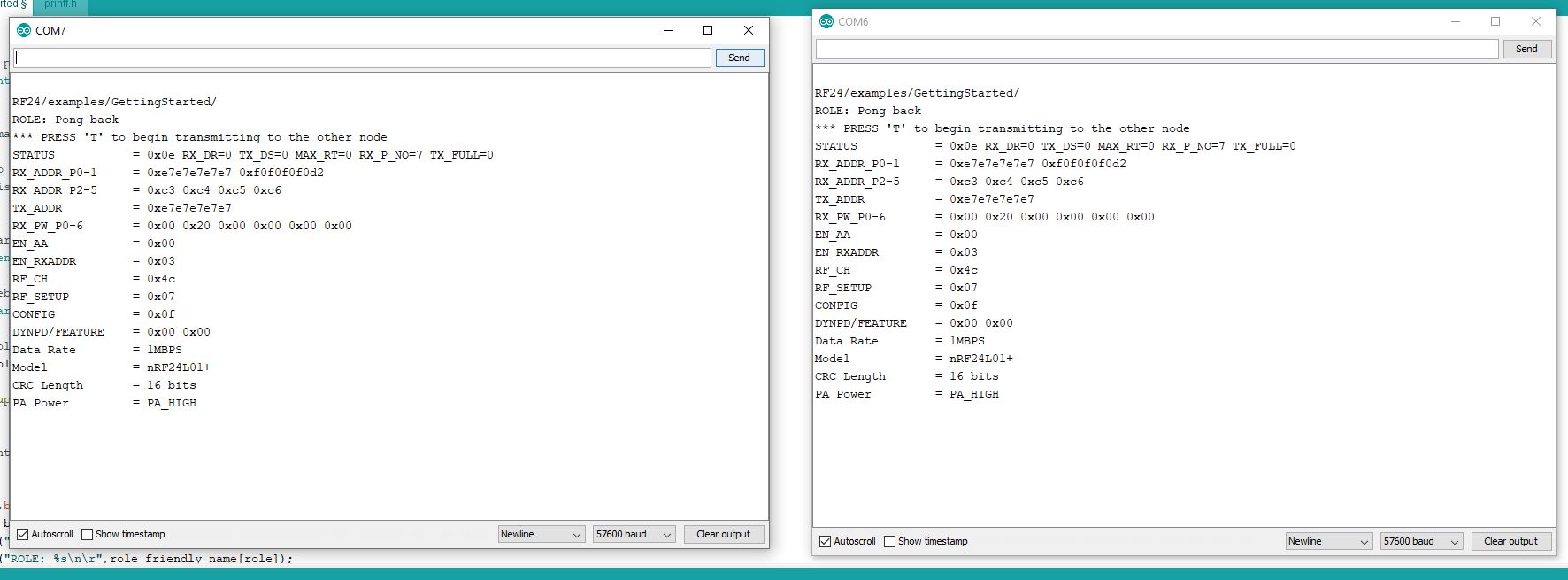
I have been trying to make it work for days, but I cant. It looks like the arduino is connecting well with the modules, but are cant figure out why they are not communicating each other.

Each one is connected in port, here are the radio.print():
Please download it, url not working.


Are the adress wrong?

Here the code I am using:

/*
 Copyright (C) 2011 J. Coliz <maniacbug@ymail.com>

 This program is free software; you can redistribute it and/or
 modify it under the terms of the GNU General Public License
 version 2 as published by the Free Software Foundation.
 */

/**
 * Example for Getting Started with nRF24L01+ radios. 
 *
 * This is an example of how to use the RF24 class.  Write this sketch to two 
 * different nodes.  Put one of the nodes into 'transmit' mode by connecting 
 * with the serial monitor and sending a 'T'.  The ping node sends the current 
 * time to the pong node, which responds by sending the value back.  The ping 
 * node can then see how long the whole cycle took.
 */

#include <SPI.h>
#include "nRF24L01.h"
#include "RF24.h"
#include "printf.h"

//
// Hardware configuration
//

// Set up nRF24L01 radio on SPI bus plus pins 9 & 10 

RF24 radio(9,10);

//
// Topology
//

// Radio pipe addresses for the 2 nodes to communicate.
const uint64_t pipes[2] = { 0xF0F0F0F0E1LL, 0xF0F0F0F0D2LL };

//
// Role management
//
// Set up role.  This sketch uses the same software for all the nodes
// in this system.  Doing so greatly simplifies testing.  
//

// The various roles supported by this sketch
typedef enum { role_ping_out = 1, role_pong_back } role_e;

// The debug-friendly names of those roles
const char* role_friendly_name[] = { "invalid", "Ping out", "Pong back"};

// The role of the current running sketch
role_e role = role_pong_back;

void setup(void)
{
  //
  // Print preamble
  //

  Serial.begin(57600);
  printf_begin();
  printf("\n\rRF24/examples/GettingStarted/\n\r");
  printf("ROLE: %s\n\r",role_friendly_name[role]);
  printf("*** PRESS 'T' to begin transmitting to the other node\n\r");

  //
  // Setup and configure rf radio
  //

  radio.begin();
  radio.setAutoAck(false); 

  // optionally, increase the delay between retries & # of retries
  radio.setRetries(15,15);

  // optionally, reduce the payload size.  seems to
  // improve reliability
  //radio.setPayloadSize(8);

  //
  // Open pipes to other nodes for communication
  //

  // This simple sketch opens two pipes for these two nodes to communicate
  // back and forth.
  // Open 'our' pipe for writing
  // Open the 'other' pipe for reading, in position #1 (we can have up to 5 pipes open for reading)

  //if ( role == role_ping_out )
  {
    //radio.openWritingPipe(pipes[0]);
    radio.openReadingPipe(1,pipes[1]);
  }
  //else
  {
    //radio.openWritingPipe(pipes[1]);
    //radio.openReadingPipe(1,pipes[0]);
  }

  //
  // Start listening
  //

  radio.startListening();

  //
  // Dump the configuration of the rf unit for debugging
  //

  radio.printDetails();
}

void loop(void)
{
  //
  // Ping out role.  Repeatedly send the current time
  //

  if (role == role_ping_out)
  {
    // First, stop listening so we can talk.
    radio.stopListening();

    // Take the time, and send it.  This will block until complete
    unsigned long time = millis();
    printf("Now sending %lu...",time);
    bool ok = radio.write( &time, sizeof(unsigned long) );
    
    if (ok)
      printf("ok...");
    else
      printf("failed.\n\r");

    // Now, continue listening
    radio.startListening();

    // Wait here until we get a response, or timeout (250ms)
    unsigned long started_waiting_at = millis();
    bool timeout = false;
    while ( ! radio.available() && ! timeout )
      if (millis() - started_waiting_at > 200 )
        timeout = true;

    // Describe the results
    if ( timeout )
    {
      printf("Failed, response timed out.\n\r");
    }
    else
    {
      // Grab the response, compare, and send to debugging spew
      unsigned long got_time;
      radio.read( &got_time, sizeof(unsigned long) );

      // Spew it
      printf("Got response %lu, round-trip delay: %lu\n\r",got_time,millis()-got_time);
    }

    // Try again 1s later
    delay(1000);
  }

  //
  // Pong back role.  Receive each packet, dump it out, and send it back
  //

  if ( role == role_pong_back )
  {
    // if there is data ready
    if ( radio.available() )
    {
      // Dump the payloads until we've gotten everything
      unsigned long got_time;
      bool done = false;
      while (!done)
      {
        // Fetch the payload, and see if this was the last one.
        done = radio.read( &got_time, sizeof(unsigned long) );

        // Spew it
        printf("Got payload %lu...",got_time);

 // Delay just a little bit to let the other unit
 // make the transition to receiver
 delay(20);
      }

      // First, stop listening so we can talk
      radio.stopListening();

      // Send the final one back.
      radio.write( &got_time, sizeof(unsigned long) );
      printf("Sent response.\n\r");

      // Now, resume listening so we catch the next packets.
      radio.startListening();
    }
  }

  //
  // Change roles
  //

  if ( Serial.available() )
  {
    char c = toupper(Serial.read());
    if ( c == 'T' && role == role_pong_back )
    {
      printf("*** CHANGING TO TRANSMIT ROLE -- PRESS 'R' TO SWITCH BACK\n\r");

      // Become the primary transmitter (ping out)
      role = role_ping_out;
      radio.openWritingPipe(pipes[0]);
      radio.openReadingPipe(1,pipes[1]);
    }
    else if ( c == 'R' && role == role_ping_out )
    {
      printf("*** CHANGING TO RECEIVE ROLE -- PRESS 'T' TO SWITCH BACK\n\r");
      
      // Become the primary receiver (pong back)
      role = role_pong_back;
      radio.openWritingPipe(pipes[1]);
      radio.openReadingPipe(1,pipes[0]);
    }
  }
}
// vim:cin:ai:sts=2 sw=2 ft=cpp

Have a look at this Simple nRF24L01+ Tutorial.

Please note that it uses the newer TMRh20 version of the RF24 library. Unfortunately TMRh20 did not think to change the name for his version so it is easy to get them confused. If in doubt I suggest you delete the library completely and then download and install the TMRh20 version.

Wireless problems can be very difficult to debug so get the wireless part working on its own before you start adding any other features.

The examples are as simple as I could make them and they have worked for other Forum members. If you get stuck it will be easier to help with code that I am familiar with. Start by getting the first example to work

There is also a connection test program to check that the Arduino can talk to the nRF24 it is connected to.

...R

Okay. I read all the tutorial and tried the codes. It did not work. The transmitter looks like it is working:

TX Output:

Data Sent Message 0 Acknowledge received
Data Sent Message 1 Acknowledge received
Data Sent Message 2 Acknowledge received
Data Sent Message 3 Acknowledge received
Data Sent Message 4 Acknowledge received
.....

RX Output:

SimpleRx Starting
And then nothing happens. It does not receive any data :confused:

Here is the RX code:

// SimpleRx - the slave or the receiver

#include <SPI.h>
#include <nRF24L01.h>
#include <RF24.h>
#include "printf.h"

#define CE_PIN   7
#define CSN_PIN 8

const byte thisSlaveAddress[5] = {'R','x','A','A','A'};

RF24 radio(CE_PIN, CSN_PIN);

char dataReceived[10]; // this must match dataToSend in the TX
bool newData = false;

//===========

void setup() {

    Serial.begin(9600);

    Serial.println("SimpleRx Starting");
    radio.begin();
    radio.setPALevel(RF24_PA_LOW);
    printf_begin();
    radio.setAutoAck(false); 
    radio.setDataRate( RF24_250KBPS );
    radio.openReadingPipe(1, thisSlaveAddress);
    radio.startListening();
    radio.printDetails();

}

//=============

void loop() {
    getData();
    showData();
}

//==============

void getData() {
    if ( radio.available() ) {
        radio.read( &dataReceived, sizeof(dataReceived) );
        newData = true;
    }
}

void showData() {
    if (newData == true) {
        Serial.print("Data received ");
        Serial.println(dataReceived);
        newData = false;
    }
}

Here is the output for the diagnostic code:

Obs.: I am using Antena+Nrf24+Adpter
5V

TX:

STATUS		 = 0x0e RX_DR=0 TX_DS=0 MAX_RT=0 RX_P_NO=7 TX_FULL=0
RX_ADDR_P0-1	 = 0x4141417852 0x4141417852
RX_ADDR_P2-5	 = 0xc3 0xc4 0xc5 0xc6
TX_ADDR		 = 0x4141417852
RX_PW_P0-6	 = 0x20 0x20 0x00 0x00 0x00 0x00
EN_AA		 = 0x00
EN_RXADDR	 = 0x02
RF_CH		 = 0x4c
RF_SETUP	 = 0x23
CONFIG		 = 0x0f
DYNPD/FEATURE	 = 0x00 0x00
Data Rate	 = 250KBPS
Model		 = nRF24L01+
CRC Length	 = 16 bits
PA Power	 = PA_LOW

RX

STATUS		 = 0x0e RX_DR=0 TX_DS=0 MAX_RT=0 RX_P_NO=7 TX_FULL=0
RX_ADDR_P0-1	 = 0xe7e7e7e7e7 0x4141417852
RX_ADDR_P2-5	 = 0xc3 0xc4 0xc5 0xc6
TX_ADDR		 = 0xe7e7e7e7e7
RX_PW_P0-6	 = 0x00 0x20 0x00 0x00 0x00 0x00
EN_AA		 = 0x00
EN_RXADDR	 = 0x02
RF_CH		 = 0x4c
RF_SETUP	 = 0x23
CONFIG		 = 0x0f
DYNPD/FEATURE	 = 0x00 0x00
Data Rate	 = 250KBPS
Model		 = nRF24L01+
CRC Length	 = 16 bits
PA Power	 = PA_LOW

Do you thnk is there something wrong between the NRF24 and Arduino?

TX

Did you delete the ManiacBug RF24 library and install the TMRh20 version?

If you have not done so try de-powering (and re-powering) each Arduino after uploading the SimpleTx and Rx programs to make sure the nRF24 resets.

Do you have a 3rd nRF24 that you can try in case one of the first pair is faulty? (The connection test program does not test the wireless).

If you need more help please try the programs from my Tutorial with NO CHANGES

...R

So, I made as the turorial says, here are the evidences:

Hardware: UNO + Adapater + NRF24+ + Antenna
9V battery connected to the adapter (5-12v in / 3.3v out)

Adapter MO -> Pin 11
Adapter M1 -> Pin 12

Wiring was double checked twice (four checked then kkk)

  1. Deleted all the 3party libs

  2. Installed RF24 last release

  3. TX code

// SimpleTx - the master or the transmitter

#include <SPI.h>
#include <nRF24L01.h>
#include <RF24.h>


#define CE_PIN   9
#define CSN_PIN 10

const byte slaveAddress[5] = {'R','x','A','A','A'};


RF24 radio(CE_PIN, CSN_PIN); // Create a Radio

char dataToSend[10] = "Message 0";
char txNum = '0';


unsigned long currentMillis;
unsigned long prevMillis;
unsigned long txIntervalMillis = 1000; // send once per second


void setup() {

    Serial.begin(9600);

    Serial.println("SimpleTx Starting");

    radio.begin();
    radio.setDataRate( RF24_250KBPS );
    radio.setRetries(3,5); // delay, count
    radio.openWritingPipe(slaveAddress);
}

//====================

void loop() {
    currentMillis = millis();
    if (currentMillis - prevMillis >= txIntervalMillis) {
        send();
        prevMillis = millis();
    }
}

//====================

void send() {

    bool rslt;
    rslt = radio.write( &dataToSend, sizeof(dataToSend) );
        // Always use sizeof() as it gives the size as the number of bytes.
        // For example if dataToSend was an int sizeof() would correctly return 2

    Serial.print("Data Sent ");
    Serial.print(dataToSend);
    if (rslt) {
        Serial.println("  Acknowledge received");
        updateMessage();
    }
    else {
        Serial.println("  Tx failed");
    }
}

//================

void updateMessage() {
        // so you can see that new data is being sent
    txNum += 1;
    if (txNum > '9') {
        txNum = '0';
    }
    dataToSend[8] = txNum;
}
  1. TX Output
SimpleTx Starting
Data Sent Message 0  Tx failed

Turn off/on, connect/disconnect arduino and module, nothing changed.
Changed the module: keeps Data Sent Message 0 Tx failed

  1. Checking connection with tutorials code:

[/ode]
// 18 Mar 2018 - simple program to verify connection between Arduino
// and nRF24L01+
// This program does NOT attempt any communication with another nRF24

#include <SPI.h>
#include <nRF24L01.h>
#include <RF24.h>

#include <printf.h>

#define CE_PIN 9
#define CSN_PIN 10

const byte thisSlaveAddress[5] = {'R','x','A','A','A'};

RF24 radio(CE_PIN, CSN_PIN);

char dataReceived[10]; // this must match dataToSend in the TX
bool newData = false;

void setup() {
Serial.begin(9600);
printf_begin();

Serial.println("CheckConnection Starting");
Serial.println();
Serial.println("FIRST WITH THE DEFAULT ADDRESSES after power on");
Serial.println(" Note that RF24 does NOT reset when Arduino resets - only when power is removed");
Serial.println(" If the numbers are mostly 0x00 or 0xff it means that the Arduino is not");
Serial.println(" communicating with the nRF24");
Serial.println();
radio.begin();
radio.printDetails();
Serial.println();
Serial.println();
Serial.println("AND NOW WITH ADDRESS AAAxR 0x41 41 41 78 52 ON P1");
Serial.println(" and 250KBPS data rate");
Serial.println();
radio.openReadingPipe(1, thisSlaveAddress);
radio.setDataRate( RF24_250KBPS );
radio.printDetails();
Serial.println();
Serial.println();
}

void loop() {

}
[/code]

  1. Connectio Output for Module 01 (I have three)
    First one:
CheckConnection Starting

FIRST WITH THE DEFAULT ADDRESSES after power on
  Note that RF24 does NOT reset when Arduino resets - only when power is removed
  If the numbers are mostly 0x00 or 0xff it means that the Arduino is not
     communicating with the nRF24

STATUS		 = 0x00 RX_DR=0 TX_DS=0 MAX_RT=0 RX_P_NO=0 TX_FULL=0
RX_ADDR_P0-1	 = 0x0000000000 0x0000000000
RX_ADDR_P2-5	 = 0x00 0x00 0x00 0x00
TX_ADDR		 = 0x0000000000
RX_PW_P0-6	 = 0x00 0x00 0x00 0x00 0x00 0x00
EN_AA		 = 0x00
EN_RXADDR	 = 0x00
RF_CH		 = 0x00
RF_SETUP	 = 0x00
CONFIG		 = 0x00
DYNPD/FEATURE	 = 0x00 0x00
Data Rate	 = 1MBPS
Model		 = nRF24L01
CRC Length	 = Disabled
PA Power	 = PA_MIN


AND NOW WITH ADDRESS AAAxR  0x41 41 41 78 52   ON P1
 and 250KBPS data rate

STATUS		 = 0x00 RX_DR=0 TX_DS=0 MAX_RT=0 RX_P_NO=0 TX_FULL=0
RX_ADDR_P0-1	 = 0x0000000000 0x0000000000
RX_ADDR_P2-5	 = 0x00 0x00 0x00 0x00
TX_ADDR		 = 0x0000000000
RX_PW_P0-6	 = 0x00 0x00 0x00 0x00 0x00 0x00
EN_AA		 = 0x00
EN_RXADDR	 = 0x00
RF_CH		 = 0x00
RF_SETUP	 = 0x00
CONFIG		 = 0x00
DYNPD/FEATURE	 = 0x00 0x00
Data Rate	 = 1MBPS
Model		 = nRF24L01
CRC Length	 = Disabled
PA Power	 = PA_MIN

As we can see - it is not connected, but for our surprise the other two modules geve us the folling output:

Module 02

CheckConnection Starting

FIRST WITH THE DEFAULT ADDRESSES after power on
  Note that RF24 does NOT reset when Arduino resets - only when power is removed
  If the numbers are mostly 0x00 or 0xff it means that the Arduino is not
     communicating with the nRF24

STATUS		 = 0x0e RX_DR=0 TX_DS=0 MAX_RT=0 RX_P_NO=7 TX_FULL=0
RX_ADDR_P0-1	 = 0xe7e7e7e7e7 0x4141417852
RX_ADDR_P2-5	 = 0xc3 0xc4 0xc5 0xc6
TX_ADDR		 = 0xe7e7e7e7e7
RX_PW_P0-6	 = 0x00 0x20 0x00 0x00 0x00 0x00
EN_AA		 = 0x3f
EN_RXADDR	 = 0x03
RF_CH		 = 0x4c
RF_SETUP	 = 0x07
CONFIG		 = 0x0e
DYNPD/FEATURE	 = 0x00 0x00
Data Rate	 = 1MBPS
Model		 = nRF24L01+
CRC Length	 = 16 bits
PA Power	 = PA_MAX


AND NOW WITH ADDRESS AAAxR  0x41 41 41 78 52   ON P1
 and 250KBPS data rate

STATUS		 = 0x0e RX_DR=0 TX_DS=0 MAX_RT=0 RX_P_NO=7 TX_FULL=0
RX_ADDR_P0-1	 = 0xe7e7e7e7e7 0x4141417852
RX_ADDR_P2-5	 = 0xc3 0xc4 0xc5 0xc6
TX_ADDR		 = 0xe7e7e7e7e7
RX_PW_P0-6	 = 0x00 0x20 0x00 0x00 0x00 0x00
EN_AA		 = 0x3f
EN_RXADDR	 = 0x03
RF_CH		 = 0x4c
RF_SETUP	 = 0x27
CONFIG		 = 0x0e
DYNPD/FEATURE	 = 0x00 0x00
Data Rate	 = 250KBPS
Model		 = nRF24L01+
CRC Length	 = 16 bits
PA Power	 = PA_MAX

Module 03

CheckConnection Starting

FIRST WITH THE DEFAULT ADDRESSES after power on
  Note that RF24 does NOT reset when Arduino resets - only when power is removed
  If the numbers are mostly 0x00 or 0xff it means that the Arduino is not
     communicating with the nRF24

STATUS		 = 0x0e RX_DR=0 TX_DS=0 MAX_RT=0 RX_P_NO=7 TX_FULL=0
RX_ADDR_P0-1	 = 0xe7e7e7e7e7 0xc2c2c2c2c2
RX_ADDR_P2-5	 = 0xc3 0xc4 0xc5 0xc6
TX_ADDR		 = 0xe7e7e7e7e7
RX_PW_P0-6	 = 0x00 0x00 0x00 0x00 0x00 0x00
EN_AA		 = 0x3f
EN_RXADDR	 = 0x03
RF_CH		 = 0x4c
RF_SETUP	 = 0x07
CONFIG		 = 0x0e
DYNPD/FEATURE	 = 0x00 0x00
Data Rate	 = 1MBPS
Model		 = nRF24L01+
CRC Length	 = 16 bits
PA Power	 = PA_MAX


AND NOW WITH ADDRESS AAAxR  0x41 41 41 78 52   ON P1
 and 250KBPS data rate

STATUS		 = 0x0e RX_DR=0 TX_DS=0 MAX_RT=0 RX_P_NO=7 TX_FULL=0
RX_ADDR_P0-1	 = 0xe7e7e7e7e7 0x4141417852
RX_ADDR_P2-5	 = 0xc3 0xc4 0xc5 0xc6
TX_ADDR		 = 0xe7e7e7e7e7
RX_PW_P0-6	 = 0x00 0x20 0x00 0x00 0x00 0x00
EN_AA		 = 0x3f
EN_RXADDR	 = 0x03
RF_CH		 = 0x4c
RF_SETUP	 = 0x27
CONFIG		 = 0x0e
DYNPD/FEATURE	 = 0x00 0x00
Data Rate	 = 250KBPS
Model		 = nRF24L01+
CRC Length	 = 16 bits
PA Power	 = PA_MAX

I tested the TX code with all the three modules, any of them sent any data.

So, what should I do now? Thanks for your help.

Based on the output you have provided Module1 is not talking to its Arduino.

What does this mean?

Adapter MO -> Pin 11
Adapter M1 -> Pin 12

What adapter are you using?

...R

LOSIMONASSI:
Hardware: UNO + Adapater + NRF24+ + Antenna
9V battery connected to the adapter (5-12v in / 3.3v out)

That is a PA+LNA power hungry module combinded with a flimsy supply.
I would suggest a supply capable of providing more current,
like two AA cells, a single lithium cell, ..

Robin2:
Based on the output you have provided Module1 is not talking to its Arduino.

What does this mean?
What adapter are you using?

...R

The same as this guy: https://www.youtube.com/watch?v=57pdX6b0sfw&t=519s

I bought it thinking it would be easy like in the video lol

LOSIMONASSI:
The same as this guy:

Please just post a link to the datasheet for the device. I'm not watching 12 minutes of YouTube.

...R

That is the one I bought.

LOSIMONASSI:
That is the one I bought.

It states "Current: 12.3 mA" but I have no idea what that refers to. Assuming it is the current available for the nRF24 then it is much too low - by a factor of at least 20 I reckon.

As @Whandall has suggested try powering the nRF24 with a pair of AA alkaline cells (3v) with the battery GND connected to the Arduino GND.

...R