The NRF24L01 usual topic

Good Morning..
Like all of the fellow arduinist guys I have some problems with that small modules that claim to transfer data with simple text programming... :o

Nahhh this isn't my case...

Let's start from the beginning

I have the following parts :

  • 2 x GeekCreit arduino UNO
  • 1 x Genuine arduino Uno
  • 2 x Aideepen NRF24L01+
  • 2 x Generic NRF24L01+ 2.4GHz
  • 2 x 6v 10uf capacitor
  • 2 x Power Supply Motherboards
  • 6 x Com ports
  • 3 x USB cables

STEPS

  1. I found the most proposed tutorial and start step by step give life to those little modules...

http://forum.arduino.cc/index.php?topic=421081

  1. Installed https://tmrh20.github.io/RF24/ library

  2. Rebooted

  3. Made the wiring according to the tutorial. the wire colors are the same with the tutorial for easier debbuging

  1. Added a 10uf capacitor with the correct polarity close to the NRF module 3.3v and ground

  2. Open arduino and uploaded this code that its for NRF24 connection testing

// 18 Mar 2018 - simple program to verify connection between Arduino
//      and nRF24L01+
//  This program does NOT attempt any communication with another nRF24

#include <SPI.h>
#include <nRF24L01.h>
#include <RF24.h>

#include <printf.h>

#define CE_PIN   9
#define CSN_PIN 10

const byte thisSlaveAddress[5] = {'R','x','A','A','A'};

RF24 radio(CE_PIN, CSN_PIN);

char dataReceived[10]; // this must match dataToSend in the TX
bool newData = false;


void setup() {
    Serial.begin(9600);
    printf_begin();

    Serial.println("CheckConnection Starting");
    Serial.println();
    Serial.println("FIRST WITH THE DEFAULT ADDRESSES after power on");
    Serial.println("  Note that RF24 does NOT reset when Arduino resets - only when power is removed");
    Serial.println("  If the numbers are mostly 0x00 or 0xff it means that the Arduino is not");
    Serial.println("     communicating with the nRF24");
    Serial.println();
    radio.begin();
    radio.printDetails();
    Serial.println();
    Serial.println();
    Serial.println("AND NOW WITH ADDRESS AAAxR  0x41 41 41 78 52   ON P1");
    Serial.println(" and 250KBPS data rate");
    Serial.println();
    radio.openReadingPipe(1, thisSlaveAddress);
    radio.setDataRate( RF24_250KBPS );
    radio.printDetails();
    Serial.println();
    Serial.println();
}


void loop() {

}

The result of this as expected is this and believe that its ok?

CheckConnection Starting

FIRST WITH THE DEFAULT ADDRESSES after power on
Note that RF24 does NOT reset when Arduino resets - only when power is removed
If the numbers are mostly 0x00 or 0xff it means that the Arduino is not
communicating with the nRF24

STATUS = 0x0e RX_DR=0 TX_DS=0 MAX_RT=0 RX_P_NO=7 TX_FULL=0
RX_ADDR_P0-1 = 0x65646f4e31 0x4141417852
RX_ADDR_P2-5 = 0xc3 0xc4 0xc5 0xc6
TX_ADDR = 0x65646f4e31
RX_PW_P0-6 = 0x20 0x20 0x00 0x00 0x00 0x00
EN_AA = 0x3f
EN_RXADDR = 0x02
RF_CH = 0x4c
RF_SETUP = 0x03
CONFIG = 0x0e
DYNPD/FEATURE = 0x00 0x00
Data Rate = 1MBPS
Model = nRF24L01+
CRC Length = 16 bits
PA Power = PA_LOW

AND NOW WITH ADDRESS AAAxR 0x41 41 41 78 52 ON P1
and 250KBPS data rate

STATUS = 0x0e RX_DR=0 TX_DS=0 MAX_RT=0 RX_P_NO=7 TX_FULL=0
RX_ADDR_P0-1 = 0x65646f4e31 0x4141417852
RX_ADDR_P2-5 = 0xc3 0xc4 0xc5 0xc6
TX_ADDR = 0x65646f4e31
RX_PW_P0-6 = 0x20 0x20 0x00 0x00 0x00 0x00
EN_AA = 0x3f
EN_RXADDR = 0x02
RF_CH = 0x4c
RF_SETUP = 0x23
CONFIG = 0x0e
DYNPD/FEATURE = 0x00 0x00
Data Rate = 250KBPS
Model = nRF24L01+
CRC Length = 16 bits
PA Power = PA_LOW

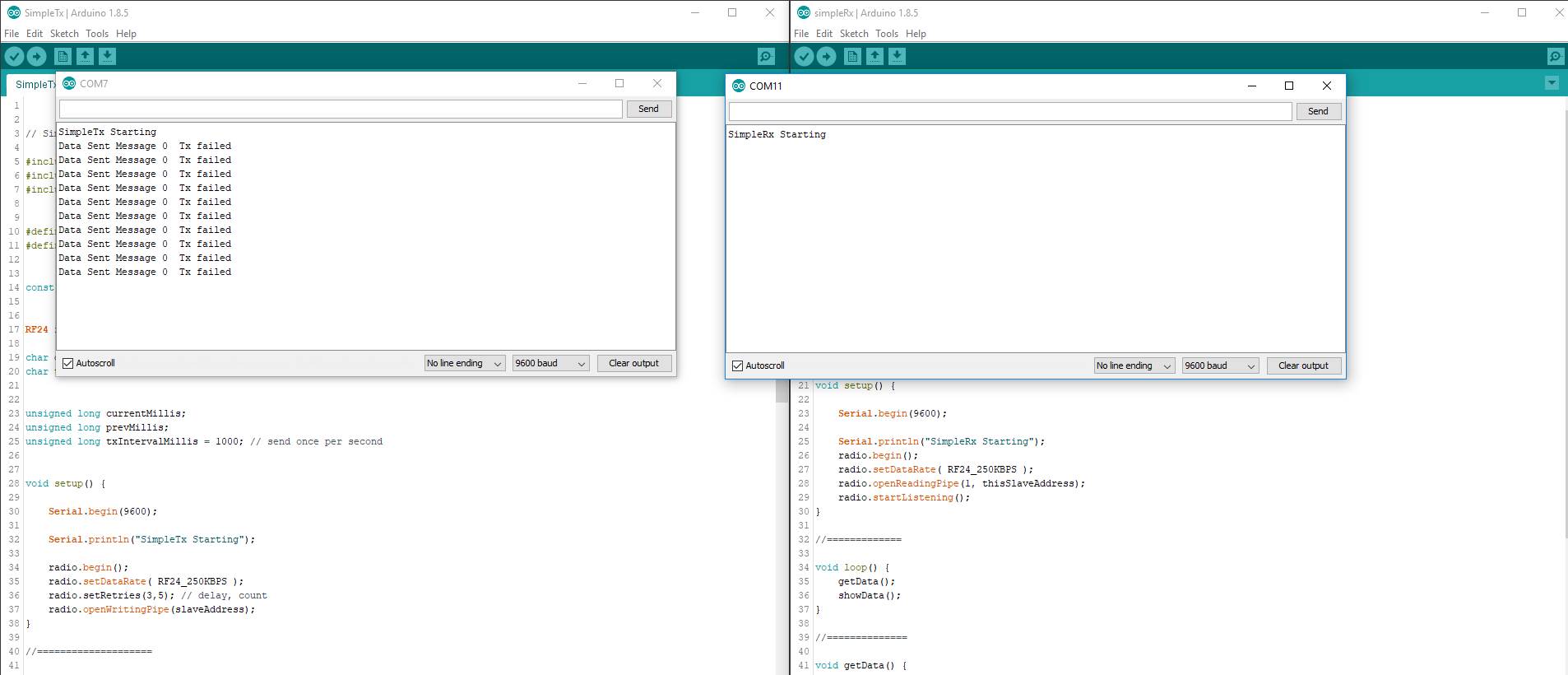
  1. Time for the SIMPLE TX code
// SimpleTx - the master or the transmitter

#include <SPI.h>
#include <nRF24L01.h>
#include <RF24.h>


#define CE_PIN   9
#define CSN_PIN 10

const byte slaveAddress[5] = {'R','x','A','A','A'};


RF24 radio(CE_PIN, CSN_PIN); // Create a Radio

char dataToSend[10] = "Message 0";
char txNum = '0';


unsigned long currentMillis;
unsigned long prevMillis;
unsigned long txIntervalMillis = 1000; // send once per second


void setup() {

    Serial.begin(9600);

    Serial.println("SimpleTx Starting");

    radio.begin();
    radio.setDataRate( RF24_250KBPS );
    radio.setRetries(3,5); // delay, count
    radio.openWritingPipe(slaveAddress);
}

//====================

void loop() {
    currentMillis = millis();
    if (currentMillis - prevMillis >= txIntervalMillis) {
        send();
        prevMillis = millis();
    }
}

//====================

void send() {

    bool rslt;
    rslt = radio.write( &dataToSend, sizeof(dataToSend) );
        // Always use sizeof() as it gives the size as the number of bytes.
        // For example if dataToSend was an int sizeof() would correctly return 2

    Serial.print("Data Sent ");
    Serial.print(dataToSend);
    if (rslt) {
        Serial.println("  Acknowledge received");
        updateMessage();
    }
    else {
        Serial.println("  Tx failed");
    }
}

//================

void updateMessage() {
        // so you can see that new data is being sent
    txNum += 1;
    if (txNum > '9') {
        txNum = '0';
    }
    dataToSend[8] = txNum;
}

The result of this wasn't the expected on...

TROUBLESHOOTING

  1. Tried All 4 module , with all the cables , different com ports and all the arduino uno I have! (more than 20 combinations!!)

  2. removed the capacitor

  3. used power board for 3.3volt and connected only the nrf module there with and without the capacitor

  4. rebooted many times

  5. change the dupont cables with new one....

ANY IDEAS? :slight_smile: :slight_smile: :slight_smile:

Debugging wireless problems can be very tedious and there is no alternative to a very methodical approach.

Never change more than one thing at a time.

Have you run the connection-test program with both nRF24/Arduinos ?

Assuming you have and the SimpleTx / SimpleRx programs are not working then please post the two programs that YOU have uploaded to your Arduinos.

And post a sample of the output you get from both of them. Make sure to say how often the messages appear - they should be about once per second. Really fast repeats mean something is not working.

I have a Mega clone that does not provide enough 3.3v power for a low-power nRF24 (the one with the PCB antenna). If that might be the problem try powering your nRF24s from a pair of AA alkaline cells (3v) with the battery GND connected to the Arduino GND.

...R

Same test with a different arduino , nrf , cable and soldered capacitor.

CheckConnection Starting

FIRST WITH THE DEFAULT ADDRESSES after power on
Note that RF24 does NOT reset when Arduino resets - only when power is removed
If the numbers are mostly 0x00 or 0xff it means that the Arduino is not
communicating with the nRF24

STATUS = 0x0e RX_DR=0 TX_DS=0 MAX_RT=0 RX_P_NO=7 TX_FULL=0
RX_ADDR_P0-1 = 0xe7e7e7e7e7 0x4141417852
RX_ADDR_P2-5 = 0xc3 0xc4 0xc5 0xc6
TX_ADDR = 0xe7e7e7e7e7
RX_PW_P0-6 = 0x00 0x20 0x00 0x00 0x00 0x00
EN_AA = 0x3f
EN_RXADDR = 0x03
RF_CH = 0x4c
RF_SETUP = 0x07
CONFIG = 0x0e
DYNPD/FEATURE = 0x00 0x00
Data Rate = 1MBPS
Model = nRF24L01+
CRC Length = 16 bits
PA Power = PA_MAX

AND NOW WITH ADDRESS AAAxR 0x41 41 41 78 52 ON P1
and 250KBPS data rate

STATUS = 0x0e RX_DR=0 TX_DS=0 MAX_RT=0 RX_P_NO=7 TX_FULL=0
RX_ADDR_P0-1 = 0xe7e7e7e7e7 0x4141417852
RX_ADDR_P2-5 = 0xc3 0xc4 0xc5 0xc6
TX_ADDR = 0xe7e7e7e7e7
RX_PW_P0-6 = 0x00 0x20 0x00 0x00 0x00 0x00
EN_AA = 0x3f
EN_RXADDR = 0x03
RF_CH = 0x4c
RF_SETUP = 0x27
CONFIG = 0x0e
DYNPD/FEATURE = 0x00 0x00
Data Rate = 250KBPS
Model = nRF24L01+
CRC Length = 16 bits
PA Power = PA_MAX

SimpleTx Starting
Data Sent Message 0 Tx failed

maybe the capacitors are not good?

Robin2:
Debugging wireless problems can be very tedious and there is no alternative to a very methodical approach.

Never change more than one thing at a time.

Have you run the connection-test program with both nRF24/Arduinos ?

Assuming you have and the SimpleTx / SimpleRx programs are not working then please post the two programs that YOU have uploaded to your Arduinos.

And post a sample of the output you get from both of them. Make sure to say how often the messages appear - they should be about once per second. Really fast repeats mean something is not working.

I have a Mega clone that does not provide enough 3.3v power for a low-power nRF24 (the one with the PCB antenna). If that might be the problem try powering your nRF24s from a pair of AA alkaline cells (3v) with the battery GND connected to the Arduino GND.

...R

thanks for the reply sir.

have tried now to power the nrf from a usb powered powersupply motherboard. I connect the ground from the nrf to the arduino.

Still the same tx failure.

I attach the two ino files that are used

TestNRF.ino (1.32 KB)

SimpleTx.ino (1.48 KB)

upload two both arduino.

the com7 is on power board
the com11 is on arduino 3.3v with capacitor

same results... #4 attachment is the serial output

Slow down a bit. I can't keep up.

Kolokotronis:
Still the same tx failure.

I attach the two ino files that are used

I am not surprised that the TX is failing as you are not using it with the matching RX program.

...R

Robin2:
Slow down a bit. I can't keep up.

I am not surprised that the TX is failing as you are not using it with the matching RX program.

...R

slow down request approved...

But I am using the two examples from the tutorial. SimpleTx and SimpleRx

Tx is still saying Failed.

But the Receiver says Data Received.

the fun part is that I disconnect the Transmitter and the Receiver continues saying Data Received...

SimpleTx.ino (1.48 KB)

simpleTX.ino (1.48 KB)

Kolokotronis:
But I am using the two examples from the tutorial. SimpleTx and SimpleRx

That's not what you attached to Reply #3 and I can only go on what you tell me.

Tx is still saying Failed.

But the Receiver says Data Received.

That is technically possible if the acknowledgement does not work

the fun part is that I disconnect the Transmitter and the Receiver continues saying Data Received...

How frequent are the Data Received messages? They should be about one per second. If they repeat very quickly it usually means a problem between the Arduino and its nRF24.

Note that in Reply #1 I asked you to post a sample of the output from both Arduinos but you have not done so.

...R

Robin2:
Note that in Reply #1 I asked you to post a sample of the output from both Arduinos but you have not done so.

...R

Good morning Sir.
I have attached in messages #4 and #6 screen shots of the output of both arduino. Do you ask for something else?

the messages are printed about 1 every half a second. should I add a delay to the loop code?

thanks for your replies

Please don't post pictures of text. Just copy and paste the text.

should I add a delay to the loop code?

Make NO changes to the code in my tutorial until you get the system working.

NOTE that the program called simpleRx.ino in your Reply #6 is actually the Tx program. If you expect to get a working program you will need to be a great deal more careful. Computers just do what you tell them even if they are told to do something stupid.

Let's start over. In your next Reply post the two programs exactly as YOU have uploaded them and post samples of the output from the two programs.

...R

Start over

Didn't understand If you need the code or the ino file so I will do both

  1. Upload SimpleTx.Ino at arduino COM 8
// SimpleTx - the master or the transmitter

#include <SPI.h>
#include <nRF24L01.h>
#include <RF24.h>


#define CE_PIN   9
#define CSN_PIN 10

const byte slaveAddress[5] = {'R','x','A','A','A'};


RF24 radio(CE_PIN, CSN_PIN); // Create a Radio

char dataToSend[10] = "Message 0";
char txNum = '0';


unsigned long currentMillis;
unsigned long prevMillis;
unsigned long txIntervalMillis = 1000; // send once per second


void setup() {

    Serial.begin(9600);

    Serial.println("SimpleTx Starting");

    radio.begin();
    radio.setDataRate( RF24_250KBPS );
    radio.setRetries(3,5); // delay, count
    radio.openWritingPipe(slaveAddress);
}

//====================

void loop() {
    currentMillis = millis();
    if (currentMillis - prevMillis >= txIntervalMillis) {
        send();
        prevMillis = millis();
    }
}

//====================

void send() {

    bool rslt;
    rslt = radio.write( &dataToSend, sizeof(dataToSend) );
        // Always use sizeof() as it gives the size as the number of bytes.
        // For example if dataToSend was an int sizeof() would correctly return 2

    Serial.print("Data Sent ");
    Serial.print(dataToSend);
    if (rslt) {
        Serial.println("  Acknowledge received");
        updateMessage();
    }
    else {
        Serial.println("  Tx failed");
    }
}

//================

void updateMessage() {
        // so you can see that new data is being sent
    txNum += 1;
    if (txNum > '9') {
        txNum = '0';
    }
    dataToSend[8] = txNum;
}

2)upload SimpleRx.ino at arduino at COM7

// SimpleRx - the slave or the receiver

#include <SPI.h>
#include <nRF24L01.h>
#include <RF24.h>

#define CE_PIN   9
#define CSN_PIN 10

const byte thisSlaveAddress[5] = {'R','x','A','A','A'};

RF24 radio(CE_PIN, CSN_PIN);

char dataReceived[10]; // this must match dataToSend in the TX
bool newData = false;

//===========

void setup() {

    Serial.begin(9600);

    Serial.println("SimpleRx Starting");
    radio.begin();
    radio.setDataRate( RF24_250KBPS );
    radio.openReadingPipe(1, thisSlaveAddress);
    radio.startListening();
}

//=============

void loop() {
    getData();
    showData();
}

//==============

void getData() {
    if ( radio.available() ) {
        radio.read( &dataReceived, sizeof(dataReceived) );
        newData = true;
    }
}

void showData() {
    if (newData == true) {
        Serial.print("Data received ");
        Serial.println(dataReceived);
        newData = false;
    }
}

3)Serial Port Output

COM7
SIMPLERX STARTING

COM12
SimpleTx Starting
Data Sent Message 0 Tx failed

  1. RX led is blinking on COM12

@UPDATE
after 1 minute

COM7
SIMPLERX STARTING
DATA RECEIVED
DATA RECEIVED

COM12
SimpleTx Starting
Data Sent Message 0 Tx failed

the "DATA RECEIVED" has a rate of 5hz.
the RX led on COM7 is STEADY ON
the RX led on COM12 is blinking

simpleRx.ino (933 Bytes)

SimpleTx.ino (1.48 KB)

Kolokotronis:
Didn't understand If you need the code or the ino file so I will do both

I sincerely hope they are identical.

And you still seem to be getting your details mucked up. Details matter for programming.

Upload SimpleTx.Ino at arduino COM 8

COM12
SimpleTx Starting

Have you powered down the Arduinos after you uploaded the program? That is necessary to make the nRF24 reset.

Does the Rx keep printing messages if you turn off the Tx? If so it means there is a problem between the Arduino and the Rx.

Make a simple pencil drawing showing how you have everything connected and post a photo of the drawing.

...R