nrf24l01 driving me crazy

Hello everybody, I have been working on this issues for days, but I can't seem to solve it in any way. I want to simply connect two arduinos via radio communication, using the nrf24l01 module. This worked a couple weeks ago, but now it somehow looks impossible.
I have tried:
-4 different nrf24l01 modules
-4 different arduinos (3 mega, 1 Uno)
-I have checked every jumper individually

And I have had no success whatsoever.

I am using the codes from this tutorial: Simple nRF24L01+ 2.4GHz transceiver demo - Exhibition / Gallery - Arduino Forum
I used the "CheckConnections" code, and everything looks fine from the results. However, if I try the "SimpleTx" code all I get is: "Data Sent Message 0 Tx failed".

I am really clueless. Is it possible that all 4 modules are not working? This seems unlikely to me. Any help would really be appreciated.
Something strange I noticed is that sometimes I get the "Acknowledge received" message if I disconnect the CE or CSN pin, but maybe this is just an artifact and nothing gets actually transmitted (indeed I don't see anything at the receiving end).

These are the codes I am using:

Check connection

// 18 Mar 2018 - simple program to verify connection between Arduino
//      and nRF24L01+
//  This program does NOT attempt any communication with another nRF24

#include <SPI.h>
#include <nRF24L01.h>
#include <RF24.h>

#include <printf.h>

#define CE_PIN   7
#define CSN_PIN  8

const byte thisSlaveAddress[5] = {'R','x','A','A','A'};

RF24 radio(CE_PIN, CSN_PIN);

char dataReceived[10]; // this must match dataToSend in the TX
bool newData = false;


void setup() {
    Serial.begin(9600);
    printf_begin();

    Serial.println("CheckConnection Starting");
    Serial.println();
    Serial.println("FIRST WITH THE DEFAULT ADDRESSES after power on");
    Serial.println("  Note that RF24 does NOT reset when Arduino resets - only when power is removed");
    Serial.println("  If the numbers are mostly 0x00 or 0xff it means that the Arduino is not");
    Serial.println("     communicating with the nRF24");
    Serial.println();
    radio.begin();
    radio.printDetails();
    Serial.println();
    Serial.println();
    Serial.println("AND NOW WITH ADDRESS AAAxR  0x41 41 41 78 52   ON P1");
    Serial.println(" and 250KBPS data rate");
    Serial.println();
    radio.openReadingPipe(1, thisSlaveAddress);
    radio.setPALevel(RF24_PA_MIN);
    radio.setDataRate( RF24_250KBPS );
    radio.printDetails();
    Serial.println();
    Serial.println();
}


void loop() {

}

SimpleTx

// SimpleTx - the master or the transmitter

#include <SPI.h>
#include <nRF24L01.h>
#include <RF24.h>


#define CE_PIN   7
#define CSN_PIN 8

const byte slaveAddress[5] = {'R','x','A','A','A'};


RF24 radio(CE_PIN, CSN_PIN); // Create a Radio

char dataToSend[10] = "Message 0";
char txNum = '0';


unsigned long currentMillis;
unsigned long prevMillis;
unsigned long txIntervalMillis = 1000; // send once per second


void setup() {

    Serial.begin(9600);

    Serial.println("SimpleTx Starting");

    radio.begin();
    radio.setDataRate( RF24_250KBPS );
    radio.setPALevel(RF24_PA_MIN);
    radio.setRetries(3,5); // delay, count
    radio.openWritingPipe(slaveAddress);
}

//====================

void loop() {
    currentMillis = millis();
    if (currentMillis - prevMillis >= txIntervalMillis) {
        send();
        prevMillis = millis();
    }
}

//====================

void send() {

    bool rslt;
    rslt = radio.write( &dataToSend, sizeof(dataToSend) );
        // Always use sizeof() as it gives the size as the number of bytes.
        // For example if dataToSend was an int sizeof() would correctly return 2

    Serial.print("Data Sent ");
    Serial.print(dataToSend);
    if (rslt) {
        Serial.println("  Acknowledge received");
        updateMessage();
    }
    else {
        Serial.println("  Tx failed");
    }
}

//================

void updateMessage() {
        // so you can see that new data is being sent
    txNum += 1;
    if (txNum > '9') {
        txNum = '0';
    }
    dataToSend[8] = txNum;
}

SimpleRx

// SimpleRx - the slave or the receiver

#include <SPI.h>
#include <nRF24L01.h>
#include <RF24.h>

#define CE_PIN   7
#define CSN_PIN  8

const byte thisSlaveAddress[5] = {'R','x','A','A','A'};

RF24 radio(CE_PIN, CSN_PIN);

char dataReceived[10]; // this must match dataToSend in the TX
bool newData = false;

//===========

void setup() {

    Serial.begin(9600);

    Serial.println("SimpleRx Starting");
    radio.begin();
    radio.setDataRate( RF24_250KBPS );
    radio.setPALevel(RF24_PA_MIN);
    radio.openReadingPipe(1, thisSlaveAddress);
    radio.startListening();
}

//=============

void loop() {
    getData();
    showData();
}

//==============

void getData() {
    if ( radio.available() ) {
        radio.read( &dataReceived, sizeof(dataReceived) );
        newData = true;
    }
}

void showData() {
    if (newData == true) {
        Serial.print("Data received ");
        Serial.println(dataReceived);
        newData = false;
    }
}

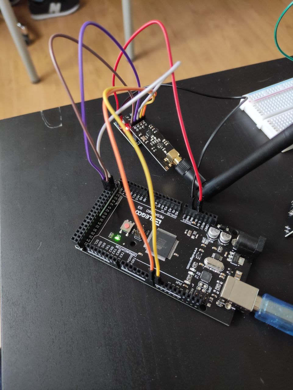
Finally, here is the photo of the setup (very basic, actually)

You appear to have changed the pins compared to my Tutorial. When you are having trouble make sure that your test is EXACTLY the same as the tutorial examples.

Your photo shows you using a high-power nRF24 (with external antenna). If you have a pair of the low power modules (with PCB antenna) I suggest you start with them. The code will be identical.

If you only have the high-power modules I suggest you separate them by about 3 metres in case the high power is overwhelming the receiver.

How are you powering the nRF24s? Lack of sufficient current can be a problem. I suggest you try powering them with a pair of AA alkaline cells (3v) for initial testing.

Please post an example of the output from the connection test program.

You have told us the output from your Tx program. What is the corresponding output from the Rx program?

...R

Robin2:
You appear to have changed the pins compared to my Tutorial. When you are having trouble make sure that your test is EXACTLY the same as the tutorial examples.

Your photo shows you using a high-power nRF24 (with external antenna). If you have a pair of the low power modules (with PCB antenna) I suggest you start with them. The code will be identical.

If you only have the high-power modules I suggest you separate them by about 3 metres in case the high power is overwhelming the receiver.

How are you powering the nRF24s? Lack of sufficient current can be a problem. I suggest you try powering them with a pair of AA alkaline cells (3v) for initial testing.

Please post an example of the output from the connection test program.

You have told us the output from your Tx program. What is the corresponding output from the Rx program?

...R

Thank you very much for the answer, Robin.
You raised very interesting points, however I don't think they are the fundamental issue here. Indeed, I have tried the same identical setup some weeks ago, with two high power modules connected to my computer, and it worked smoothly. I just set the transmission power to the minimum to lower the requirements. Unfortunately, I only have these high power modules available, so I can't try the other ones.
Furthermore, the transmission fails even if I have only one Arduino connected (so I try transmitting without receiving).

As for the SimpleRx program, there is no output at all.
This is instead the output of the "CheckConnection" code.
Transmitter:

14:57:56.035 -> FIRST WITH THE DEFAULT ADDRESSES after power on
14:57:56.082 ->   Note that RF24 does NOT reset when Arduino resets - only when power is removed
14:57:56.175 ->   If the numbers are mostly 0x00 or 0xff it means that the Arduino is not
14:57:56.269 ->      communicating with the nRF24
14:57:56.316 -> 
14:57:56.316 -> SPI Speedz	= 10 Mhz
14:57:56.316 -> STATUS		= 0x0e RX_DR=0 TX_DS=0 MAX_RT=0 RX_P_NO=7 TX_FULL=0
14:57:56.363 -> RX_ADDR_P0-1	= 0xe7e7e7e7e7 0x4141417852
14:57:56.409 -> RX_ADDR_P2-5	= 0xc3 0xc4 0xc5 0xc6
14:57:56.456 -> TX_ADDR		= 0xe7e7e7e7e7
14:57:56.504 -> RX_PW_P0-6	= 0x20 0x20 0x20 0x20 0x20 0x20
14:57:56.568 -> EN_AA		= 0x3f
14:57:56.568 -> EN_RXADDR	= 0x00
14:57:56.568 -> RF_CH		= 0x4c
14:57:56.568 -> RF_SETUP	= 0x07
14:57:56.598 -> CONFIG		= 0x0e
14:57:56.645 -> DYNPD/FEATURE	= 0x00 0x00
14:57:56.645 -> Data Rate	= 1 MBPS
14:57:56.691 -> Model		= nRF24L01+
14:57:56.691 -> CRC Length	= 16 bits
14:57:56.691 -> PA Power	= PA_MAX
14:57:56.737 -> ARC		= 0
14:57:56.737 -> 
14:57:56.737 -> 
14:57:56.737 -> AND NOW WITH ADDRESS AAAxR  0x41 41 41 78 52   ON P1
14:57:56.784 ->  and 250KBPS data rate
14:57:56.831 -> 
14:57:56.831 -> SPI Speedz	= 10 Mhz
14:57:56.831 -> STATUS		= 0x0e RX_DR=0 TX_DS=0 MAX_RT=0 RX_P_NO=7 TX_FULL=0
14:57:56.925 -> RX_ADDR_P0-1	= 0xe7e7e7e7e7 0x4141417852
14:57:56.971 -> RX_ADDR_P2-5	= 0xc3 0xc4 0xc5 0xc6
14:57:57.017 -> TX_ADDR		= 0xe7e7e7e7e7
14:57:57.017 -> RX_PW_P0-6	= 0x20 0x20 0x20 0x20 0x20 0x20
14:57:57.064 -> EN_AA		= 0x3f
14:57:57.064 -> EN_RXADDR	= 0x02
14:57:57.111 -> RF_CH		= 0x4c
14:57:57.111 -> RF_SETUP	= 0x27
14:57:57.158 -> CONFIG		= 0x0e
14:57:57.158 -> DYNPD/FEATURE	= 0x00 0x00
14:57:57.158 -> Data Rate	= 250 KBPS
14:57:57.205 -> Model		= nRF24L01+
14:57:57.205 -> CRC Length	= 16 bits
14:57:57.251 -> PA Power	= PA_MAX
14:57:57.251 -> ARC		= 0

Receiver

15:01:44.906 -> FIRST WITH THE DEFAULT ADDRESSES after power on
15:01:44.953 ->   Note that RF24 does NOT reset when Arduino resets - only when power is removed
15:01:45.046 ->   If the numbers are mostly 0x00 or 0xff it means that the Arduino is not
15:01:45.137 ->      communicating with the nRF24
15:01:45.137 -> 
15:01:45.137 -> SPI Speedz	= 10 Mhz
15:01:45.195 -> STATUS		= 0x0e RX_DR=0 TX_DS=0 MAX_RT=0 RX_P_NO=7 TX_FULL=0
15:01:45.232 -> RX_ADDR_P0-1	= 0xe7e7e7e7e7 0xc2c2c2c2c2
15:01:45.280 -> RX_ADDR_P2-5	= 0xc3 0xc4 0xc5 0xc6
15:01:45.329 -> TX_ADDR		= 0xe7e7e7e7e7
15:01:45.329 -> RX_PW_P0-6	= 0x20 0x20 0x20 0x20 0x20 0x20
15:01:45.374 -> EN_AA		= 0x3f
15:01:45.421 -> EN_RXADDR	= 0x00
15:01:45.421 -> RF_CH		= 0x4c
15:01:45.467 -> RF_SETUP	= 0x07
15:01:45.467 -> CONFIG		= 0x0e
15:01:45.467 -> DYNPD/FEATURE	= 0x00 0x00
15:01:45.512 -> Data Rate	= 1 MBPS
15:01:45.512 -> Model		= nRF24L01+
15:01:45.559 -> CRC Length	= 16 bits
15:01:45.559 -> PA Power	= PA_MAX
15:01:45.606 -> ARC		= 0
15:01:45.606 -> 
15:01:45.606 -> 
15:01:45.606 -> AND NOW WITH ADDRESS AAAxR  0x41 41 41 78 52   ON P1
15:01:45.654 ->  and 250KBPS data rate
15:01:45.700 -> 
15:01:45.700 -> SPI Speedz	= 10 Mhz
15:01:45.700 -> STATUS		= 0x0e RX_DR=0 TX_DS=0 MAX_RT=0 RX_P_NO=7 TX_FULL=0
15:01:45.793 -> RX_ADDR_P0-1	= 0xe7e7e7e7e7 0x4141417852
15:01:45.793 -> RX_ADDR_P2-5	= 0xc3 0xc4 0xc5 0xc6
15:01:45.839 -> TX_ADDR		= 0xe7e7e7e7e7
15:01:45.886 -> RX_PW_P0-6	= 0x20 0x20 0x20 0x20 0x20 0x20
15:01:45.932 -> EN_AA		= 0x3f
15:01:45.932 -> EN_RXADDR	= 0x02
15:01:45.978 -> RF_CH		= 0x4c
15:01:45.978 -> RF_SETUP	= 0x27
15:01:45.978 -> CONFIG		= 0x0e
15:01:46.025 -> DYNPD/FEATURE	= 0x00 0x00
15:01:46.025 -> Data Rate	= 250 KBPS
15:01:46.072 -> Model		= nRF24L01+
15:01:46.072 -> CRC Length	= 16 bits
15:01:46.119 -> PA Power	= PA_MAX
15:01:46.119 -> ARC		= 0

The connection tests seem OK.

There should at least be a start up message from the Rx Arduino.

Can you describe this in more detail

Indeed, I have tried the same identical setup some weeks ago, with two high power modules connected to my computer,

And tell us what is different between that test and the present situation.

...R

Robin2:
The connection tests seem OK.

There should at least be a start up message from the Rx Arduino.

Can you describe this in more detail
And tell us what is different between that test and the present situation.

...R

The only output from the SimpleRx code is "SimpleRx Starting".
The only thing that changed from the test that worked are the boards that I am using and the radio modules. However, as I stated in the opening post, I tried multiple Arduinos and multiple modules, so it would seem unlikely that none of the combination works.
Other than that, I just updated the Arduino IDE and installed some libraries (unrelated to this module)

felixeng:
The only thing that changed from the test that worked are the boards that I am using and the radio modules.

You must understand that that means nothing to me.

It does not say what boards were used when the thing worked or what radio modules and how those differ from what you are trying now.

Also your Reply #2 said "with two high power modules connected to my computer," but you have not told us how they were connected to your computer.

...R

This topic was automatically closed 120 days after the last reply. New replies are no longer allowed.