I have bought the NRF24L01 with the antenna that as they claim goes to 1 km.
I have tested the range and unfortunately it disconnected after about 150m.
Is there something I need to do to extend the range using the code itself, or do I need need to get a hardware to make the power more powerful.
const byte address[6] = "01608";		//The communication address of the Transceiver

RF24 radio(10, 9); 						//CE, CSN of the NRF24L01

int data[7];							//The data array to be sent

radio.begin();							//Radio
radio.openWritingPipe(address);
radio.setDataRate(RF24_250KBPS);
radio.setPALevel(RF24_PA_HIGH);
radio.stopListening();
I have only used these commands (And ofc changed them according to the Tx or Rx)
I have connected an LED on the receiver side and and when I move a joystick on the controller, the light gets turned on.
Does this have to do with anything about the array?
Or should I use a pipe instead of address?
Or do I need to use another hardware to amplify the signal?
Or do I need to add a bobin as someone suggested?
Or I am missing something in the code?
Do both transmitter and receiver have antennas?
Schematics showing how the devices are powered would be good to look into.
Whar was the terrain between the 2 devices?
You tried but that's not schematics. Pin numbers/names give o overwiew.
Also voltages, ampere capacity of the power plants ought to be checked up.
Pen and paper usually works well enough.
I would like to check if there's a powering issue.
@Railroader I am not sure of what difference it would make if I gave you the schematics, because I would just draw the parts connected to the pins that I have already mentioned before.
Or do you need something else? could you please describe what schematics you are looking for?
@mrburnette The batteries are new and charged.
Do I need to set both the transmitter and receiver at PA_MAX?
I have already done that but some people say that I should put the transmitter on MIN
Are you trying to power the radio from a pin on the Arduino?
We ask for a real schematic, even if you just draw it with a pencil and shoot a picture of it. That's actually the fastest and entirely satisfactory.
Picking apart a word description takes time. If you draw a schematic, you save everyone who has any business helping you each the time it would take them to do that. And we might make mistakes doing, or your description might have a mistake...
And does not making them at the same direction actually affects them this much?
.
.
.
I will try the range tomorrow after I have changed the PA level to MAX
That is like, I don't know what difference it would make if I gave you a hamburger instead of raw meat and flour, because I would just cook it for you.
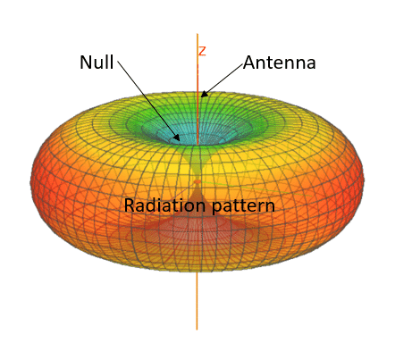
As you can see, virtually no radiation leaves in the direction where the antenna is pointing...
If you have one vertical and the other horizontal, you will still not receive much as the polarization is wrong.
So, yes this can make a huge difference.
By the way, I borrowed this pic from here Antennas for dummies | Engibex where there is much more info.
A side not to the image. That is for a true vertical dipole. The NRF antenna is just 1/2 of that dipole. The board and wiring make up the other half. Wonder if a true radiation pattern has been published for an NRF with external antenna?