I have that antenna in the pasture North of the house. A computer controlled automatic tuner at the base. Forty 38 ft. radials just under the ground surface. World wide contacts confirm the text of your document.
Many of the Nrf24 units are clones and never work as expected on long range or the claimed range.
Only seen some that actually work which were provided by reputable sellers.
More details can be accessed over where they play with converted rc gear everyday .....
One example here........
https://mode-zero.uk/viewtopic.php?f=61&t=1349&p=11531#p11531
Arduino's 3.3V pin can't provide the necessary current, not even close. It's more surprising that it works at all. A separate 3.3V power supply capable of more than 500 mA of stable, ripple-free, robust vs sharp changes of load power is a must to reach good performance
I use homemade versions of these adapters to supply adequate current and voltage, with good success.
Which Arduino would that be. OP didn't say.
An Uno/Mega has a dedicated 3.3volt/150mA regulator.
The NRF24L01 tops at 13.5mA.
Leo..
13 mA it's current for a basic nRF24 module (I think it takes more in max power TX, but that's irrelevant). OP used nRF24+LNA+PA module - the last part literally is called "Power Amplifier" and it takes a lot of power. A lot.
*as for nRF24 I was wrong, it requires 11 mA in max TX power (I mixed it with nRF52840 with its +8dBm).
But here: https://forum.mysensors.org/topic/3961/nrf24l01-pa-lna-power-consumption/42 someone measured consumption of nRF24 with PA - and they saw peak current at around 200 mA (and given the module nature, I won't be surprised to see significant unit-to-unit variation there, so anything below 300 mA is not adequate - and at 300 mA it should be well within operation range, so I'd use something with at least 500 mA rating)
If OP uses the +PA version, which OP didn't say, then transmit draws 115mA.
This is fine for an Uno/Mega, but not for a classic Nano (30mA max from 3.3volt).
What I'm trying to say is that OP didn't give us the right information to even guess what's wrong.
OP, please read the posting guidelines.
To help you we need all the information.
Leo..
There is a scope picture in that post on the link I've sent before - 700 mV on 3.4 ohm resistor, which results in a bit over 200 mA. Where did you get 115 mA from? Also, given that it was measured with such a high resistor in series, with direct connection I would expect even higher current draw.
+PA is evident from description "with the antenna, as they claim goes to 1 km" - only +PA version has external antenna and specified to work at such distance.
Sorry, I posted before reading your reply. The 115mA came from the original datasheet.
I still think 150mA from an Uno should be ok. As with any transmitter, there should be ample supply buffering. When I power a bare ESP8266 module from 3.3volt I always add at least a 470uF tantalum cap across the supply. The cap will bridge the short peak transmit currents, so the supply only has to deliver average current.
No, it's not. 1/4λ of 2.4GHz is ~3cm. Those aerials are about 7cm long and contain a full 1/2λ dipole. Actually a ~6cm long sleeve aerial, so ground plane is irrelevant. Best used pointing up, with nothing else in the horizontal plane. The board should ideally be under it, not next to it.
Leo..
I did not know they were sleeve antennas. A good omni-directional antenna design. Been used for many generations for fixed locations.
Yep, one of the first aerials I made in the sixties/seventies for a 100MHz FM radio transmitter after reading Rothammel's antenna book (aerial bible). Still have the German version on the bookshelf.
Leo..
The same batteries are connected to L289N for motors that require this much voltage.
I am not sure how to get that info tbh.
I didn't understand what ground plain mean tbh :<
You can have a look at the photos below
Homemade?
Is it just a regulator that's connected to 5v pin in Arduino?
Thanks for the info <3
I have tested the MAX settings today and the transmission went farther than before as I have expected.
But for some reason when I was getting farther from the receiver, the receiver needed a little while to actually catch up and understand that the transmitter has gotten farther than before.
Which means the turn on and offs of the light got delayed out for some seconds before the light has turned on again.
After a few seconds the light turn on and off in time.
This thing kept happening as I got further.
Therefore I think that the solution to this is to give the appropriate current through the 5v pin and through the adapter as a lot of users have said.
.
Here are the photos of the transmitter and receiver.


The pink highlight is the 3.3V connected directly, while the green highlight is GND connected to 2 joysticks and 4 buttons and the NRF
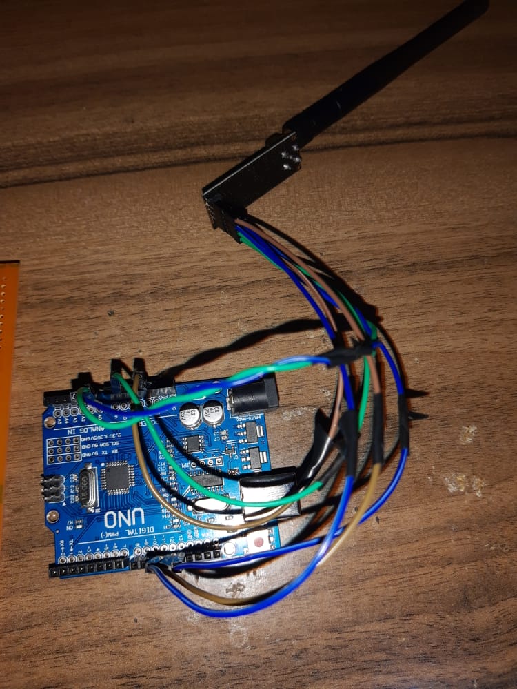
Photos?
No thank You.
Good bye.
Now, I wonder why I never dissected one of those rubber covered router antennas. I wonder if I have one in the junk boxes in the loft?
470 uF tantalum (and that's important - not electrolytic aluminium one) would work here indeed, most likely it will be fine even with Arduino's 3.3V - but not less than that. From the shape of that impulse I don't think that 100 uF would suffice, and I have doubts about 200 (although 200+ is worth a shot if OP has one at hand)
I have seen a video where someone used 100 uF and connected it to GND and VCC.
but tbh I don't know what it does.
Is there a documentation or a video that explains what capacitors are useful in the radio module?
And why do you think that 470 uF is better?
If that was ordinary nRF24 without PA then even 10 uF would work fine there.
You can estimate the necessary capacitance from several points, one is stored energy:
E=C * V^2/2
On the other hand, energy is power * time: E=I * V * t
From that image in that discussion I've linked, we can roughly estimate energy required for TX event as 0.2A * 3.3V * 0.8ms ~= 0.5 * 10^-3 J
If we want all that energy to come from capacitor, we need to take difference of capacitor voltage before and after the event:
dE = C/2 * (V1^2-V2^2)
And here we can put restriction: we want voltage on the capacitor not to drop too much. Let's say we want it to be 3.0V after the TX event. Then:
0.5 * 10^-3J = C/2 * (3.3^2-3.0^2)
0.5 * 10^-3J=C * 0.945V^2
C=0.53 * 10^-3F = 530 uF
But also a large part of that energy would be supplied by still working 3.3V LDO, so with 470 uF we likely we'll get to ~3.15-3.2V at the end, which is close enough to not impair the transmission
*I'm using V as voltage at first, and as Volt unit later, hope it's clear enough where which case is
In telecommunication, a ground plane is a flat or nearly flat horizontal conducting surface that serves as part of an antenna.
This is from Ground plane - Wikipedia
I can see from your photograph that you haven't. That will improve the performance if you fit one on both antenna.
Well a good way is to search the internet.
I thought I made it clear in post#30 that a ground plane is not needed, even unwanted, with those aerials. A 1/2λ performs best when no ground is near.
Leo..