OBD2 Freematics UART V2.1 isn't connecting

Hello everyone,

I bought the Freematics OBD2 UART V2.1 Adapter, got me a pair of DOIT ESP32 DEV KIT boards, 3 ESP32 S2-mini and some TFT 1.28' GC9A01 displays.

I know that this is an Arduino Forum but really cant figure it out and I mean I'm using Arduino IDE.

Uploaded my sketch, connected both the display and the OBD2 adapter to one of my ESP32 S2-mini and tried plugging it in to my Mini One R50 2005.

Long story short, no output on my display and yes I connected everything the right way.

Now I ask myself what Problem It could be. (I will attach my sketch at the end)

  1. It could be the Baud rate. I can't find out which Baud rate the Freematics V2.1 is using.

  2. It could be the serial.begin, so that the ESP32 S2-mini isn't even getting the data right.

  3. My Mini One R50 isn't even able to communicate with the adapter. I don't know where to look up these details and I am not even sure if they are able to be found anywhere.

My sketch for the S2-mini (I already changed the Serial.begin(Don't know if it did something)):

#include <SPI.h>
#include <Adafruit_GC9A01A.h>
#include <Adafruit_GFX.h>
#include <OBD2UART.h>

// ---------- HSPI Pins ----------
#define HSPI_MOSI 13
#define HSPI_SCK  14

// ---------- Display Pins ----------
#define CS_PIN   5
#define DC_PIN   21
#define RST_PIN  18

// ---------- Display Setup ----------
Adafruit_GC9A01A tft(CS_PIN, DC_PIN, HSPI_MOSI, HSPI_SCK, RST_PIN);
COBD obd;

// ---------- Variablen ----------
String lastText = "";

// ---------- Position ----------
int centerX = 120;
int centerY = 120;

// ---------- Fester Bereich für Zahlen ----------
int16_t valWidth = 70;
int16_t valHeight = 50;

void setup() {
  Serial1.begin(115200);
  Serial.begin(115200, SERIAL_8N1, 16, 17);

if (obd.begin()) {
  if (obd.begin()) {
    Serial.println("OBD2 verbunden!");
  }
  } else {
    Serial.println("OBD2 Adapter nicht gefunden.");
  }

  tft.begin();
  tft.setRotation(0);
  tft.fillScreen(GC9A01A_BLACK);

  // ---------- Feste Texte EINMAL zeichnen ----------
  tft.setTextSize(2);
  tft.setTextColor(GC9A01A_WHITE);

  int16_t x1, y1; uint16_t w, h;

  String header = "Geschw.";
  tft.getTextBounds(header, 0, 0, &x1, &y1, &w, &h);
  tft.setCursor(centerX - w/2, 20);
  tft.print(header);

  String unit = "km/h";
  tft.getTextBounds(unit, 0, 0, &x1, &y1, &w, &h);
  tft.setCursor(centerX - w/2, 220);
  tft.print(unit);

  // Anfangsanzeige
  drawValue("---");
}

void loop() {
  int speed = 0;
  String newText;

  if (obd.readPID(PID_SPEED, speed)) {
    newText = String(speed);   // keine führenden Nullen
  } else {
    newText = "---";           // kein Signal
  }

  if (newText != lastText) {
    drawValue(newText);
    lastText = newText;
  }

  delay(100);
}

// ---------- Zahl zeichnen (größer, mittig) ----------
void drawValue(String val) {
  tft.setTextSize(6); // größere Zahl
  tft.setTextColor(GC9A01A_WHITE, GC9A01A_BLACK); // Text + Hintergrund

  // Alte Zahl löschen
  int16_t x1, y1; uint16_t w, h;
  if (lastText != "") {
    tft.getTextBounds(lastText, 0, 0, &x1, &y1, &w, &h);
    tft.fillRect(centerX - w/2 - 5, centerY - h/2 - 5, w + 10, h + 10, GC9A01A_BLACK);
  }

  // Neue Zahl mittig berechnen
  tft.getTextBounds(val, 0, 0, &x1, &y1, &w, &h);
  tft.setCursor(centerX - w/2, centerY - h/2);
  tft.print(val);
}

Disconnect all devices and start by connecting one, likely the display and make it work. Then go for the next device.

Posting schematics is a good idea. That would help us.

1 Like

Do the sample Arduino sketches work for you?

1 Like

Forum members understand that you believe that, but it will take a wiring diagram (preferably hand drawn, with parts, pins and connections clearly labeled) and maybe even a posted pic of the setup to convince them.

For example, they've seen far too many bad header pin soldering jobs (or not soldered at all), components inserted backwards into the breadboard, etc.

1 Like

do you get any Serial monitor output?
usually I don't specify GPIO pins for Serial and use GPIO 16 and 17 for Serial1

do you get any "OBD2 verbunden!" or "OBD2 Adapter nicht gefunden." message displayed?

1 Like

Sorry I said it worng, the display is working fine, mx only problem is, that I don't get any data-output to the screen.

To be honest, I think I dont get any output but as you said, Iwill try to only use

Serial1.begin(115200, Serial_8n1, 16, 17);

or do you mean

Serial1.begin(115200);

Is that even the right Baud-rate?

Thanks for the comment!

Haven't tried it yet :slight_smile:

But the sample arduino sketch is for an Arduino and it's debug LED if I'm not wrong?

Ok, I will make one and post in here as soon as it is finished :+1:

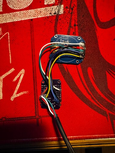
Here is the wiring diagram and a picture but to be honest, I don‘t think that you will see anything because I secured the soldering with hot glue, because the wires are cramped up in a tight space and I don’t want them to whiggle around that much.


You are correct! The bottom sides of the boards, showing the soldering, is what needs to be shown. Check for solder bridges, cold or incomplete solder joints, etc. and use your multimeter to check voltages on all pins.

Especially make sure that you are not applying 5V from the OBD-II TX to a 3.3V input on the MCU.

1 Like

looking at the circuit diagram in post 10 it looks like you have ESP32S2 GPIO16 (RX) and 17 (TX) connected to OBD2 TX and RX respectively so the pin mapping

Serial1.begin(115200, Serial_8n1, 16, 17);

should work

no idea if the baudrate is correct for the target OBD2 device
what is it? do you have a manual?

if you do a simple loopback test on GPIO16 and 17 does it work?

EDIT: thinking again OBD2 is based on the CANBUS network NOT TTL serial

have a look at Two-Wire Automotive Interface (TWAI)

1 Like

It's my first project and I don't know how to do a Loopback :grimacing:

RX and TX need to be switched around so RX and TX and TX and RX. Freematics OBD-II UART Adapter V2.1 (for Arduino) It says it like that on the page.

Thanks for the page :handshake:, looking into it.

Power is working fine and before hotglueing the soldering joints I checked for soldering bridges. I don't have a multimeter :grimacing:

But does the wiring looks fine to you?

I mean the problem isn't solved yet, but thanks already for all the help! :handshake:

looks like the device you have gives a TTL serial interface to OBD2
have you tried the ArduinoOBD library

1 Like

Isn't that the Library I'm using currently?

I definitely got that library downloaded.

To be fair I didn't got it compiling with that library at the beginning. Asked ChatGPT for help, moved somethings around in the library folder and ended up where I'm now (Where ever I am now :smiling_face_with_tear:).

upload your latest code and any serial monitor output you get?
you don't need to initialize the OBD2 serial interface - the library does it for you

1 Like

The S2-mini has the problem that it can either work, or be connected to a external device, so I can't look into the serial monitor while using it.

The code I'm currently using:

#include <SPI.h>
#include <Adafruit_GC9A01A.h>
#include <Adafruit_GFX.h>
#include <OBD2UART.h>

// ---------- HSPI Pins ----------
#define HSPI_MOSI 13
#define HSPI_SCK  14

// ---------- Display Pins ----------
#define CS_PIN   5
#define DC_PIN   21
#define RST_PIN  18

// ---------- Display Setup ----------
Adafruit_GC9A01A tft(CS_PIN, DC_PIN, HSPI_MOSI, HSPI_SCK, RST_PIN);
COBD obd;

// ---------- Variablen ----------
String lastText = "";

// ---------- Position ----------
int centerX = 120;
int centerY = 120;

// ---------- Fester Bereich für Zahlen ----------
int16_t valWidth = 70;
int16_t valHeight = 50;

void setup() {
  // USB-Monitor bleibt an Serial1 (z. B. auf Pins 9/10 oder gar nicht genutzt)
  Serial1.begin(115200);
  Serial1.println("Starte...");

  // Serial0 umleiten auf GPIO16/17 für Freematics
  Serial.end();
  Serial.begin(115200, SERIAL_8N1, 16, 17);

if (obd.begin()) {
  if (obd.begin()) {
    Serial.println("OBD2 verbunden!");
  }
  } else {
    Serial.println("OBD2 Adapter nicht gefunden.");
  }

  tft.begin();
  tft.setRotation(0);
  tft.fillScreen(GC9A01A_BLACK);

  // ---------- Feste Texte EINMAL zeichnen ----------
  tft.setTextSize(2);
  tft.setTextColor(GC9A01A_WHITE);

  int16_t x1, y1; uint16_t w, h;

  String header = "Geschw.";
  tft.getTextBounds(header, 0, 0, &x1, &y1, &w, &h);
  tft.setCursor(centerX - w/2, 20);
  tft.print(header);

  String unit = "km/h";
  tft.getTextBounds(unit, 0, 0, &x1, &y1, &w, &h);
  tft.setCursor(centerX - w/2, 220);
  tft.print(unit);

  // Anfangsanzeige
  drawValue("---");
}

void loop() {
  int speed = 0;
  String newText;

  if (obd.readPID(PID_SPEED, speed)) {
    newText = String(speed);   // keine führenden Nullen
  } else {
    newText = "---";           // kein Signal
  }

  if (newText != lastText) {
    drawValue(newText);
    lastText = newText;
  }

  delay(50);
}

// ---------- Zahl zeichnen (größer, mittig) ----------
void drawValue(String val) {
  tft.setTextSize(6); // größere Zahl
  tft.setTextColor(GC9A01A_WHITE, GC9A01A_BLACK); // Text + Hintergrund

  // Alte Zahl löschen
  int16_t x1, y1; uint16_t w, h;
  if (lastText != "") {
    tft.getTextBounds(lastText, 0, 0, &x1, &y1, &w, &h);
    tft.fillRect(centerX - w/2 - 5, centerY - h/2 - 5, w + 10, h + 10, GC9A01A_BLACK);
  }

  // Neue Zahl mittig berechnen
  tft.getTextBounds(val, 0, 0, &x1, &y1, &w, &h);
  tft.setCursor(centerX - w/2, centerY - h/2);
  tft.print(val);
}
I thought the ESP32S2 had a second hardware serial port Serial1 available for connection to external devices
the ESP32S3 certainly has

unfortunatly not.

I tried putting the serial down and then up again (the code above) with the new parameters but this also did not work.