Hello there,
I would like to connect my Arduino UNO to my car using the OBD2 K-line. I do not want to use adapters (my preference is just basic components). I have made some research but have found only

According my understanding it's wrong - when K-line is idle it will be LOW but on idle state it should be HIGH. I think that one of the transistors should be removed (with all supporting elements). In this case the K-line will be HIGH when idle. But after this RX will be constantly HIGH.
The other issue with this schematic is that RX pin is connected to 12V and could be burned.
I also have found this one
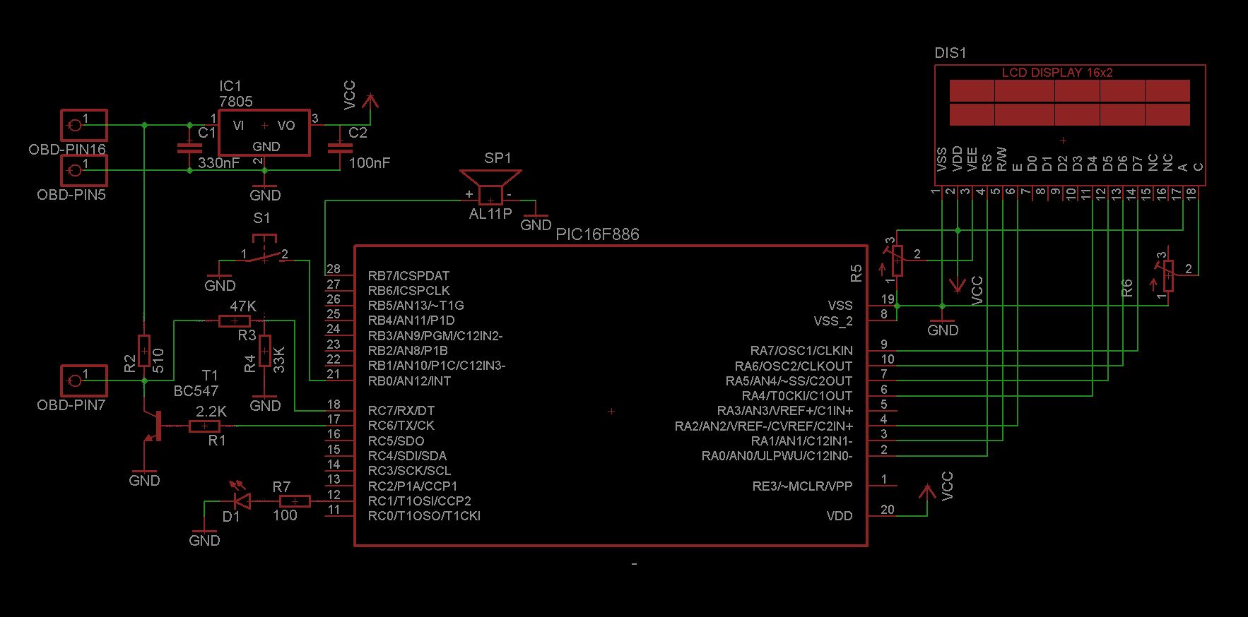
it's using PIC controller but I believe that the connection should be the same does not matter of the used controller (may be some resistors should be changed but otherwise everything else should look the same). With this one again the RX will be constantly HIGH.
The other issue with this schematic is that RX pin is connected to 12V and could be burned.
Also I can not understand the purpose of R4 resistor.
I have end up with this

but the only thing that I have solved so far is that RX pin is not connected to 12V. I still did not check what will happen if I replace R6 and R7, so R6+R7 will be big enough that after it there will be no current. In this case Q3 will not be activated (switched on) when K-line is idle but should be activated when when K-line is up.
If I'm unable to solve this issue with simple components I also have found this GitHub - iwanders/OBD9141: A class to read an ISO 9141-2 port found in OBD-II ports. but will need to change SN65HVDA195 with MC33290P (because of the packaging), so the schematic will be a little bit different (and I will have other questions in this case).
P.S. As you can see my background is not electronics and my be I'm missing some basic knowledge. Fell free to point me to materials with the basic of the electronics.