Odd behaviour of UNO LED pin

I have been playing with interrupts, learning a lot from the forum and from Nick Gammon's site.

I came across some odd behaviour in a piece of code that wrote to a pin when a button was pushed. In Nick's code, he wrote to pin 9 and had an LED wired to that pin. The UNO has an LED on pin 13, so I changed the variable to use that.

I've recast the code to delete all the interrupt code, and stopped the loop after the last pinMode change so the behaviour is the same.

const byte LED = 13;

 void setup () 
{
  pinMode(Button, INPUT_PULLUP);
}  // end of setup

void loop () 
{
  pinMode (LED, OUTPUT);
  digitalWrite (LED, HIGH);
  delay (500);
  digitalWrite (LED, LOW);
  delay (500);
  pinMode (LED, INPUT); // Oddly turns LED on. Pin reads high
  while(1);
}

The LED is toggled on and off when the loop runs as expected. But when the pin has its mode changed to INPUT, the LED turns on.

As the pin is configured as an input, I tested by using a jumper to pull pin 13 to 0V, and the LED turned off. Note that the pin is not configured to be INPUT_PULLUP, and that the line before it has it's mode changed writes a LOW to it, so I'd expect it to be at 0V or at least floating.

If I comment out the line that changes the mode, the pin measures 0V and the LED is off.

It's no problem for me, just unexpected.

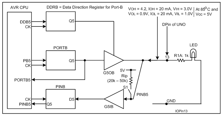
I have not been able to find a direct connection between the LED or it's bias resistor and pin 13, so there is probably a mosfet in there somewhere.

Can anyone explain what is going on or suggest what I might do next to find out?

. . . will switch on the pullup resistor of pin LED if LED is defined as an INPUT pin (at least on AVR microcontrollers as on the Uno for example).
If the led is powered via the pullup resistor it will be rather dim.

The Uno R3 has an opamp buffer between pin13 and the LED, so will probably be full brightness

1 Like

Thanks @JohnLincoln . I suspected there was something in the middle, but I couldn't see anything like an op-amp or a buffer. It isn't shown in the circuit diagrams that I have seen, but then some of them don't even show the LED...

Then if the input to that buffer floats high, it turns the LED on full.

The following diagram (Fig-1) shows that there is absolutely no active source of power to turn On LED when DPin-13 is configured to work as INPUT. Edit: Please, see post #6, 8.

Therefore, the LED is glowing just due to stray/noise signal of the environment.
I have measured/displayed the logic level of DPIn-13 by including this line: Serial.print(digitalRead(13)); in the sketch of OP (post #1), and I have found 0. When I have measured by DVM, I have got around 1V.


Figure-1:

In many AVR-controllers, the 328 on the UNO one of them, the PORT register is used to control the pull-up resistor (S1 in your diagram). So if the output was HIGH before switching to INPUT, the pull-up will be on. This reduces the number of registers but causes some confusion.

Just to throw a spanner in the works, I tried the sketch as published on a Uno R3, and the LED was off at the end.

Yes! You are correct referring to Fig-1. The LED is getting tiny current (internal pull-up = 20k - 50k) from Vcc via internal pullup. In that case, the LED should glow dim; however, it is bright in my case. (PUD = 0, Q of DDxn = 0, Q of PORTxn = 1)


Figure-1:

The LED on the UNO is controlled by a OPAMP with a very high input impedance meant not to affect the behavior of the pin. When the pin is an input without pull-up, the voltage is undefined unless something is connected to it. A small imbalance in the end transistors of the output circuitry may cause the pin to drift from 5V to 0 and back.

2 Likes

This topic was automatically closed 180 days after the last reply. New replies are no longer allowed.