On Arduino Uno with PN532 boards, they are sometimes not found when powering via USB from laptop and never found when powering via a power bank

Hi all,

I'm working on a project using an Arduino Uno, ITEAD PN532 module (datasheet), servomotors and WS2811 LEDs. I'm having issues with the stability on the PN532 boards. I would greatly appreciate any help, as I have no idea how to fix this issue.

The issue is that

  • When powered from USB connected to my laptop, the boards are found most of the time. It happens that one is not found but if I restart the board without touching any wiring, it will work
  • When powered from USB connected to a power bank, the boards are never found

By "boards are found / not found", I mean that the following code from the Adafruit_PN532 library returns (or does not return ) version data :

nfc.begin();
uint32_t versiondata = nfc.getFirmwareVersion();
if (!versiondata) {
  Serial.print("Didn't find PN53x board");
  set_error_state();
}

If the Arduino cannot connect to the board, it gets into error mode, which lights the LEDs in red and halts

void set_error_state() {
  for (int i = 0; i < NUM_LEDS; i++) {
      leds[i] = CRGB::Red; 
  }
  FastLED.show(); 
  delay(1000);
  while(1); // halt
}

This allows me to visually know that no version data was found, which means that the PN532 board was not found.

Do you have any idea of what could generate this behavior ?

More general information :

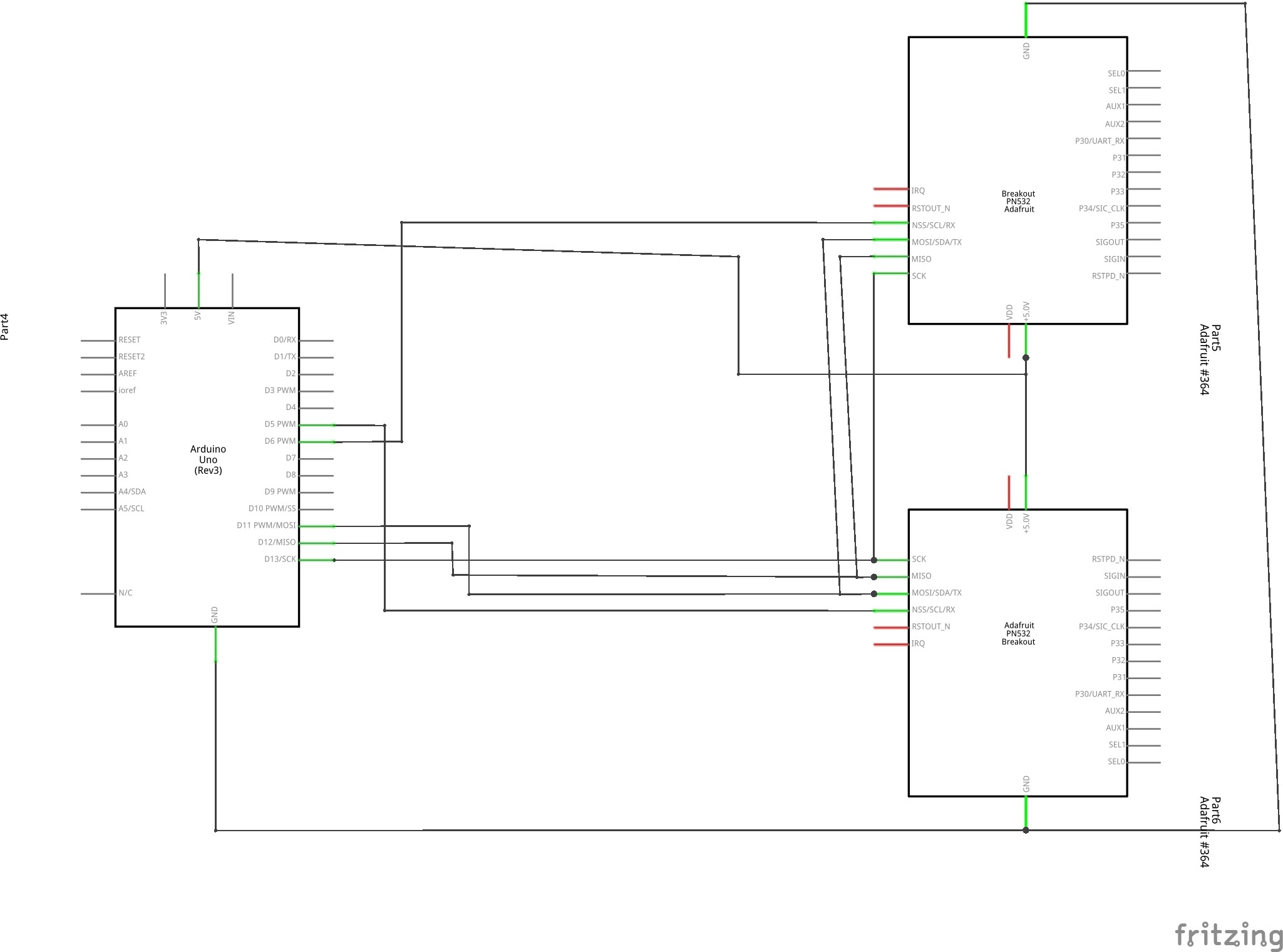
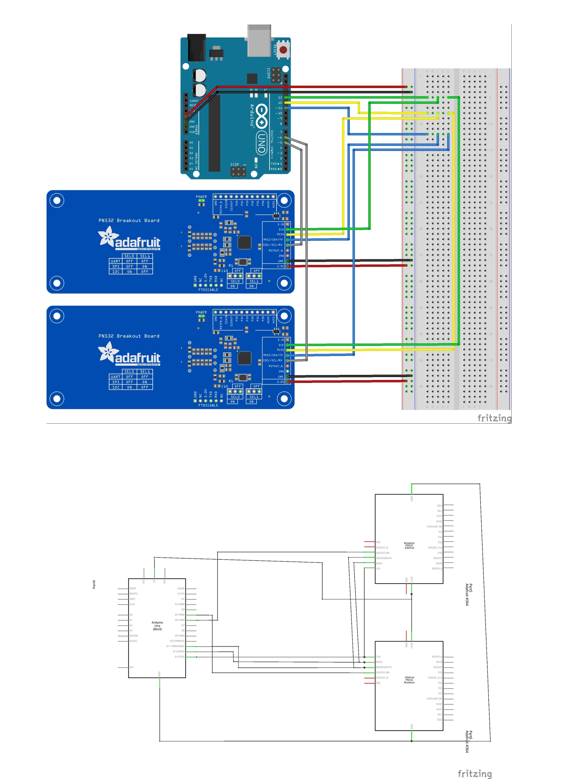
Example schematics of the wiring of multiple PN532 boards (not the entire schematics, as it misses a couple boards, it's not the exact pins I used and the other components are missing, but the general idea is there)

Here is the minimal code that I could trim down to reproduce the behavior. It's basically only the setup part

#include <Wire.h>
#include <SPI.h>
#include <Adafruit_PN532.h>
#include <FastLED.h>

FASTLED_USING_NAMESPACE

#define DATA_PIN    9
#define LED_TYPE    WS2811
#define COLOR_ORDER RGB
#define NUM_LEDS    4
CRGB leds[NUM_LEDS];

#define BRIGHTNESS          96
#define FRAMES_PER_SECOND  120

#define N_BOARDS (4)

Adafruit_PN532 nfc_1(2, 5, 3, 4);
Adafruit_PN532 nfc_2(2, 5, 3, 6);
Adafruit_PN532 nfc_3(2, 5, 3, 7);
Adafruit_PN532 nfc_4(2, 5, 3, 8);
Adafruit_PN532 boards[N_BOARDS] = {nfc_1, nfc_2, nfc_3, nfc_4};

void setup_nfc(Adafruit_PN532 nfc, int i) {
  Serial.println((String)"Setting up board #"+i);
  delay(5000);
  nfc.begin();

  uint32_t versiondata = nfc.getFirmwareVersion();
  if (!versiondata) {
    Serial.print("Didn't find PN53x board");
    set_error_state();
  }
  // Got ok data, print it out!
  Serial.print("Found chip PN5"); Serial.println((versiondata>>24) & 0xFF, HEX); 
  Serial.print("Firmware ver. "); Serial.print((versiondata>>16) & 0xFF, DEC); 
  Serial.print('.'); Serial.println((versiondata>>8) & 0xFF, DEC);
  
  // configure board to read RFID tags
  nfc.SAMConfig();
}

void set_error_state() {
  for (int i = 0; i < NUM_LEDS; i++) {
      leds[i] = CRGB::Red; 
  }
  FastLED.show(); 
  delay(1000);
  while(1); // halt
}

void setup(void) {
  Serial.begin(115200);
  while (!Serial) delay(100);

  // Setup LEDs
  FastLED.addLeds<LED_TYPE,DATA_PIN,COLOR_ORDER>(leds, NUM_LEDS).setCorrection(TypicalLEDStrip);
  FastLED.setBrightness(BRIGHTNESS);
  FastLED.clear();
  FastLED.show();

  // Setup NFC boards
  for (int i = 0; i < N_BOARDS; i++) {
    setup_nfc(boards[i], i);
  }

  delay(3000); // 3 second delay for recovery  
}

void loop(void) {
  // do stuff...
}

When not finding the boards, this would print the following and light the LEDs red

-> Setting up board #0
-> Didn't find PN53x boardError

When finding the boards, this would print

-> Setting up board #0
-> Found chip PN532
-> Firmware ver. 1.6
-> Setting up board #1
-> Found chip PN532
-> Firmware ver. 1.6
-> Setting up board #2
-> Found chip PN532
-> Firmware ver. 1.6
-> Setting up board #3
-> Found chip PN532
-> Firmware ver. 1.6

I've tried two different power banks. They both work to turn on the Arduino and then the LEDs are all turned red from the error state. The specs from the power banks are :

  • PNY M4H4 / Output : USB 5V 2.1A 5200mAh 24Wh
  • Sony CP-V3A / Output : USB 5V 1.5A 1600mAh 8.0Wh

Thank you for reading this far and helping me out :slight_smile:

Fritzing pictures are toys. No helper appreciates the detective work to get an overview. Schematics, and links to datasheets, please.

Many powerbanks require a certain amount of current (250mA) be drawn or they will shutdown, as a power-saving measure (not busy enough, 'good bye').

Kind of ties things up doesn't it?

There is not much wrong with that Fritzing. No rats nests, consistent colouring of functional lines. Only thing that is missing is where the power for the NFCs comes from.

You're welcome to dig down in it!

Thanks for looking into my issue. I'm sorry you didn't find the information I provided helpful.

I'm a hobbyist and beginner (this is my 2nd project). My ability to ask for help is limited by the extent of my knowledge.

This means that I won't be able to provide more detailed schematics. If you provide directions, I can try but there's a good chance the schematics won't be very good. I was hoping a clear Fritzing schematic would be enough, given the relative simplicity of the setup.

If that's of any help, I've found the schematics for the PN532 and for the Arduino

I've drawn schematics from the fritzing bb, let me know if this is what you were looking for

Please do tell me if there's anything I can provide that can help you to give me directions. I'll try my best to provide it.

Thanks for helping out!

If the power bank shuts down, wouldn't that mean that the Arduino should not be running anymore?

Because that is not what I'm observing. The Arduino is still running and executing code : the LEDs are turned red from the code, which seems to indicate that the Arduino is still powered and running, doesn't it ?

Regarding your comment on the setup of serial output : I'm not 100% sure I understood what you meant. Did you mean that this might be preventing the rest of the code from executing when powered by a power bank (which would not support serial output) ?

If so, I've tried removing it but the result is still the same. Also, the rest of the code seems to be executing, as I mentioned regarding the LEDs being controlled by the program running on the Arduino :confused:

Thanks for helping out ! The power for the NFCs come from the Arduino (which itself draws power from USB). Now that you point it out, I did forget to wire the breadboard 5V and GND lines to the Arduino pins :man_facepalming: I've edited my original post to fix that

Breakout Wiring | Adafruit PN532 RFID/NFC Breakout and Shield | Adafruit Learning System

"The PN532 chip and breakout is designed to be used by 3.3V systems. To use it with a 5V system such as an Arduino, a level shifter is required to convert the high voltages into 3.3V. If you have a 3.3V embedded system you won't have to use the shifter of course!"

BTW - Do you have the RFC board headers soldered in, or are you 'improvising'?

Know the importance of links to datasheets. One helper point out a serious mistake, connecting a 3.3 volt circuit to a 5 volt controller. Of course helpers can hunt datasheets but You were advised to that in the second post.

You're able! Pen and paper usually works well. The circuits doesn't need to be perfect rectangles. Pin designations, powering and the wiring are the most needed information.
Counting pins, "pin number this from the left" is useless for helpers not having that exact circuit. Bringing up datasheets to find out.... is not attractive... If You use analog input 0 just name it A0. Where that pin is located on the physical circuit is uninteresting.
The total picture, overview, is important.

Good eye! I'm actually using a PN532 compatible module. The datasheet for this module states a recommended supply power voltage 3.3~5.5V.

To be completely honest, it's my first time I'm seeing this specific datasheet. I got lucky making it work on the 5V pin before. I was assuming I could simply follow instructions for the more popular PN532 module. Sorry about that, I'm just realizing the importance of accuracy and datasheets.

However, switching from the 5V pin to the 3.3V pin on the Arduino didn't seem to change anything...

Regarding your question about the board headers : yes, there are soldered in.

100%, I'm realizing how a tiny inaccuracy can make a world of difference. I'm learning as we go.

I'm updating my original question with datasheets and schematics as the discussion progresses. Maybe now it contains the information you were initially looking for?

It's the UNO outputs being 5V and the PN352 board inputs expecting 3V.
It's concerning.

Yes, this is what I meant. I changed that and wired the 3.3V Uno output to the NFC board power input but it didn't change anything.

Also, the board I'm using seems a bit different as it only has a 5V power input pin (from the datasheet)

I read the info on the Adafruit board because that is what you had depicted the situation as.
The DOCs for the Adafruit board are a little jumbled, not their usual, but their note which I posted seems Unambiguous.

(Am I supposed to hunt out the iteadstudio DOCs now?)

Regardless. They may have much in common.
The board is powerable by 5V (possibly 3V), but either way, I suspect that the data lines are expecting 3V signals, not 5V signals.
Changing power from 5V to 3V on your board will not change that.

The Adafruit board does not come with on-board 5v/3v level shifting (conversion). Maybe iteadstudio's does, IDK.

Who says the iteadstudio board is supposed to be compatible with the Adafruit library?

My approach is to be Methodical - get one thing working and move along.

Post Edit -- "Std Raspberry Pi" interface - that's 3V signals

You are absolutely right to be methodical.

I am sorry for misleading you into looking at the Adafruit board documentation. I am learning by sharing. I am grateful that you are taking the time to help me.

My point is : I updated the wiring to match your remark. It unfortunately didn't fix the issue.

Who says the iteadstudio board is supposed to be compatible with the Adafruit library?

I could not find official sources that state this is the case. However I did manage to make it work. So it is at least somewhat compatible. Some other people on this forum seem to also have done it before. This lead me to believe that they were compatible... The issue I have now is that it's unstable and behaves differently when powered differently.

PS: I am updating the original post with this information as the conversation evolves. Thank you for leading me towards a more refined question.

It looks like nobody met with success.

"My point is : I updated the wiring to match your remark. It unfortunately didn't fix the issue.
No. I keep telling you it is NOT a matter of changing the supply voltage at '5V' to 3v. So, for the last time - whether 3V or 5V are fed to the NFC board's power input makes no difference, you are giving it 5V signals from the Arduino (if you are using a Uno, as depicted, but maybe that's different too).