Hello.
I am working on a project in which it is necessary to track the change in voltage from light, I connected an RGB LED to see how the voltage will change from one color or another. Wrote a code in processing to control the color. I want to add a photoresistor and a photodiode. As I understand it, in order for everything to work correctly, you can use the operational amplifier as a voltage follower so that there are no drawdowns, you may also need an operational amplifier for the photodiode, as it may not have enough voltage. Also I made R-2R DAC. And this is the question, I don’t quite understand how it’s better for me to connect the amplifier to the RGB LED, is it right to connect the amplifier to each leg of the LED, or maybe I’m completely wrong and I’m not thinking about what I need.
I would be grateful if you also suggest some improvements
For informed help, please post a clear, detailed description of the project goal, and a schematic diagram (hand drawn is fine) of the circuit you have constructed.
Based on the effect of photoconductivity, I want to use an RGB LED as a light source and shine it on a photoresistor and a photodiode and change the color of the glow to look at changes in voltage, resistance, etc.
I'm attaching the diagram I've assembled so far.
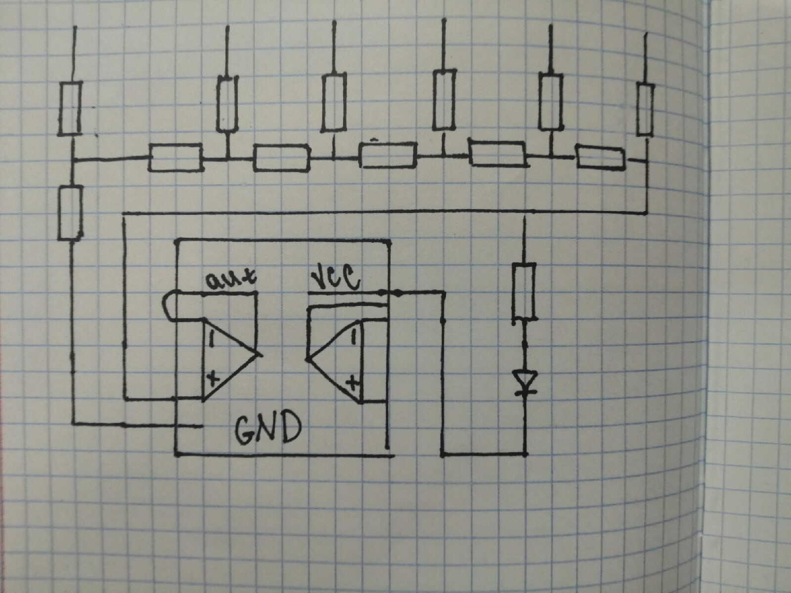
Those operational amplifier are not wired to anything on the outputs so how are they going to do any good?
Is that for the LED? To adjust the brightness?
LEDs are "current controlled". The voltage across the LED is almost constant as the brightness changes. You can change the resistance in series with an LED to vary the current.
You could do that but the non-linearity with voltage probably won't work the way you want.
Normally LEDs are dimmed with PWM which switches on & off rapidly, lowering the average voltage & current giving the perception of dimming. You can still use a phototransistor or photodiode but you'll have to do some filtering (or averaging).
A phototransistor probably just needs a resistor in series with the emitter or collector, with the output at the junction of the resistor & phototransistor. The datasheet might have a suggested schematic. And you'll probably have to experiment to find the best resistor value since you probably don't know the light level.
If you need amplification after that it only takes two resistors and an op-amp to make an amplifier and you can easily find examples on the Internet. But the slightly-tricky thing with op-amps is they normally need positive and negative power supplies. There are ways around that and there are rail-to-rail op-amps that with a single 5V supply can output the full range (or almost the full range) of 0-5V.
With the right resistor you shouldn't have any problem getting a voltage you can read with the Arduino. So an amplifier would only be useful in amplifying changes between low & high light levels.
From my limited knowledge a photodiode needs a current amplifier a (transconductance amplifier). In theory, that's simple too but I believe they need high gain (especially with low light) and when you've got high-gain any noise gets amplified and you can get "noise problems" (unstable/unreliable readings).
I connect the output to the input (-) to repeat the voltage, to equalize the voltage at the input and output and then apply power to the LED. Maybe I misunderstood something
Yes you did.
The whole point about an op amp is that the output has to be connected to something as well as back to the -ve input in order for it to do something. So the buffer or voltage follower should take its input from the output of ladder and the output should be connected to the LED.
Maybe it is not intended to do anything? A sort of WOM?
Yes, ![]()
![]() in the old days of a micro controller needing an address and data bus the only way to output anything was to use the address bus lines to map out one specific memory location, or a group and write to that address where a data latch would be attached to the data bus. That indeed was true write only memory as unless you put a tri-state buffer buffer on the data bus and attached its inputs to your data latch there was no way for the processor to acces what you have written. Such a waste of hardware very few people designed a system like this.
in the old days of a micro controller needing an address and data bus the only way to output anything was to use the address bus lines to map out one specific memory location, or a group and write to that address where a data latch would be attached to the data bus. That indeed was true write only memory as unless you put a tri-state buffer buffer on the data bus and attached its inputs to your data latch there was no way for the processor to acces what you have written. Such a waste of hardware very few people designed a system like this.