I have a series of about 22 optocouplers working as an interface for another device that outputs data in terms of 0 and 24 dc.
A very basic circuit I have is given in the attachments, just keeping 4 optocouplers to ward off the complexity.
I am using:
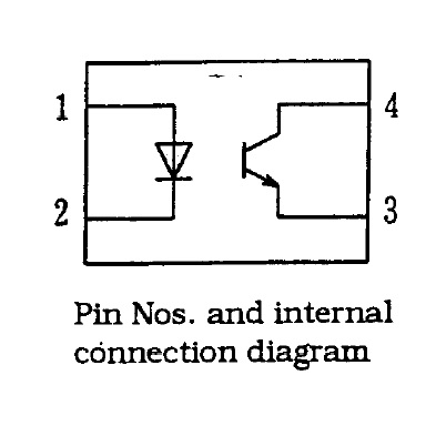
Optocoupler - PC817
Resistance - 10K 1w
MCU - ESP32
I am getting erratic outputs when reading through the pins of ESP32.
At times, when connecting the input pins through 24v power supply, some are read as 1 and some are read as 0. Even with open circuit, it is reading 1 for few while 0 for others.
To summarize, I am seeing these outputs:
Some Pins read 1 - when 24v applied to relevant OptoCoupler.
Some Pins read 0 - when 24v applied to relevant OptoCoupler.
Some Pins read 1 - even with open circuit, which means no voltage applied through OptoCoupler input.
runaway_pancake:
Your fritzing ( :puke: )
shows your coincell SHORTED!
Lol, yeah I realized that now (updated original question).
INPUT_PULLUP does work, but the problem seems to be still there. Is that because I have used common as ground and should have used VCC as common, so that if the transistor inside PC817 starts conducting, it sends 3.3v instead of grounding it, which could be read as HIGH on the input pin?
If the 10k resistors are on the input side of the opto coupler, change to 4k7 if a 24V circiut and 1k if a
5V circuit, so there's a reasonable amount of current through the device, 5mA is a sensible minimum
for most opto couplers, otherwise you'll get sluggish operation and very low output drive ability.
If you are using 10k with 5V, that's only 500µA, and opto's are typically designed for 15mA or thereabouts.
Having a lower valued input resistor allows a lower-valued pull-up resistor on the output, which means
faster switching is possible - the datasheet for the PC817 has a graph showing just how dramatic a
difference it makes, changing from 10k to 500 ohms is at least a factor of ten in speed.
The built-in pullups are 30k to 50k, so inadequate for the output of a photo coupler alone,
you need external pullups as small as you can get away with bearing in mind the input current
and current-transfer-ratio of the coupler.
Hi,
Can you draw a proper circuit diagram, showing your gnd and 3.3V, the ESP32 and the opto-coupler and how you have them connected together.
PLEASE do not use fritzy, draw it with pen/pencil and paper and send an image of it.
What do you want the input of the ESP32 to see when you apply power to the input side of the opto-coupler?
TomGeorge:
Hi,
Can you draw a proper circuit diagram, showing your gnd and 3.3V, the ESP32 and the opto-coupler and how you have them connected together.
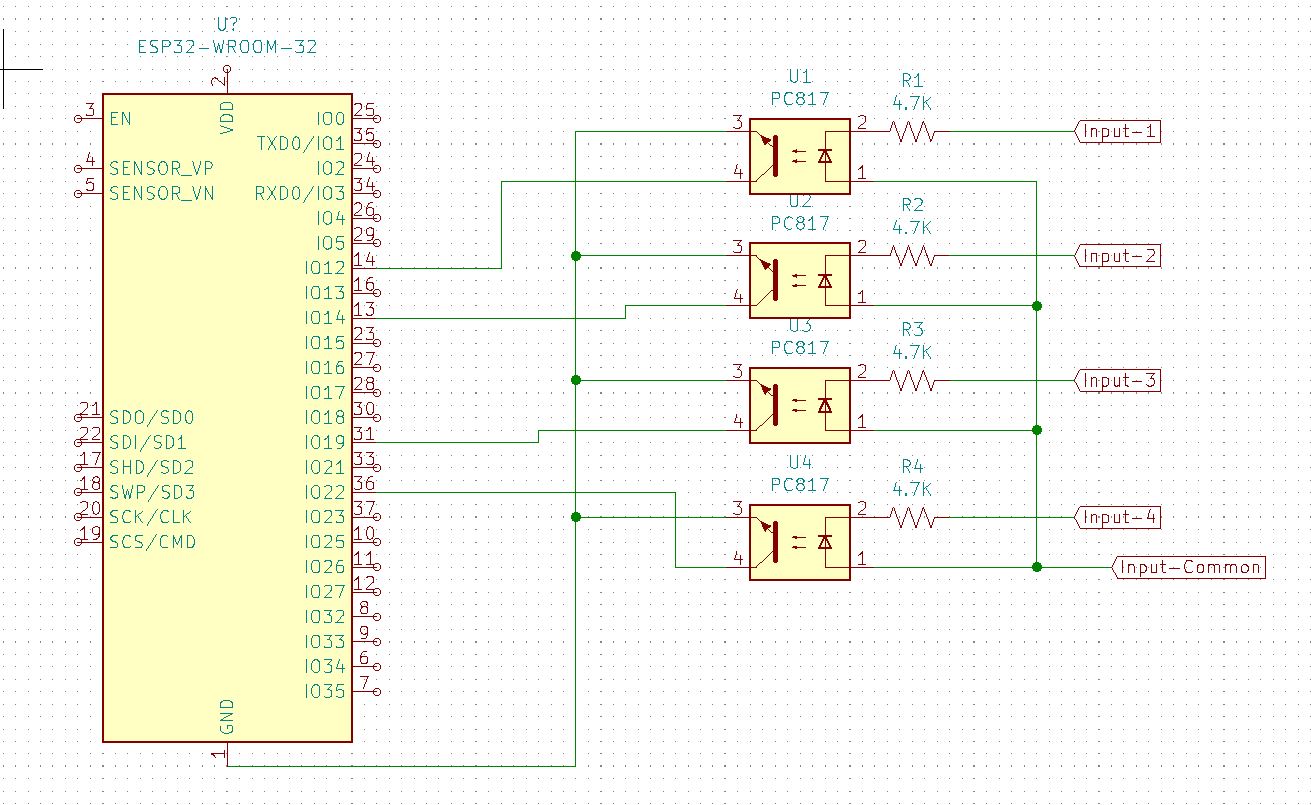
Sorry everyone for posting a confusing schematic. I've attached a better one this time.
runaway_pancake:
The emitter/s should go to GND, the collector/s should go the input/s (INPUT_PULLUP).
I see as per @runaway_pancake, I messed up where I should have connected them to GND, I used them on input pins.
MarkT:
If the 10k resistors are on the input side of the opto coupler, change to 4k7 if a 24V circiut and 1k if a
5V circuit, so there's a reasonable amount of current through the device, 5mA is a sensible minimum
for most opto couplers, otherwise you'll get sluggish operation and very low output drive ability.
@MarkT, I did calculations earlier and it was supposed to be 4.7K, but when doing the test, I wasn't able to operate the OC. To be sure, I used a 20K Potentiometer, and the OC started conducting at 10K. I know this isn't a right approach, but the calculations didn't work for me.
Is this how this should be made? I have connected all Emmitter Pins to GND this time.
You have the opto inputs (pin 1,2) hooked up backwards.
Electronics is a detail-oriented.
PE - "Common" is ordinarily, in my experience, associated with "Ground".
One exception being a power supply with an output figured as Negative (which might be labelled NEG & COM, NEG & RTN, and so on).
I won't be back in, given all the QRM and QRN that creep in when people don't stay current with their subjects, but I thought this clarification important.
Do you mean, emitters of the OC will be connected to Ground of ESP32 and the collectors will go to GPIO or the ESP board?
Yes
And you need 4.7k ohm pullup resistors on the collectors.
You need to reverse the connections on the led side of the optos.
You have the opto inputs (pin 1,2) hooked up backwards.
You have the opto OUTputs (pin 3,4) hooked up backwards.
If you rotate the opto vertically 180 degrees , it will be correct (except for the missing pullups, which you can
fix with Input Pullup config in setup.)