Hi There!
Thank you for reading my question.
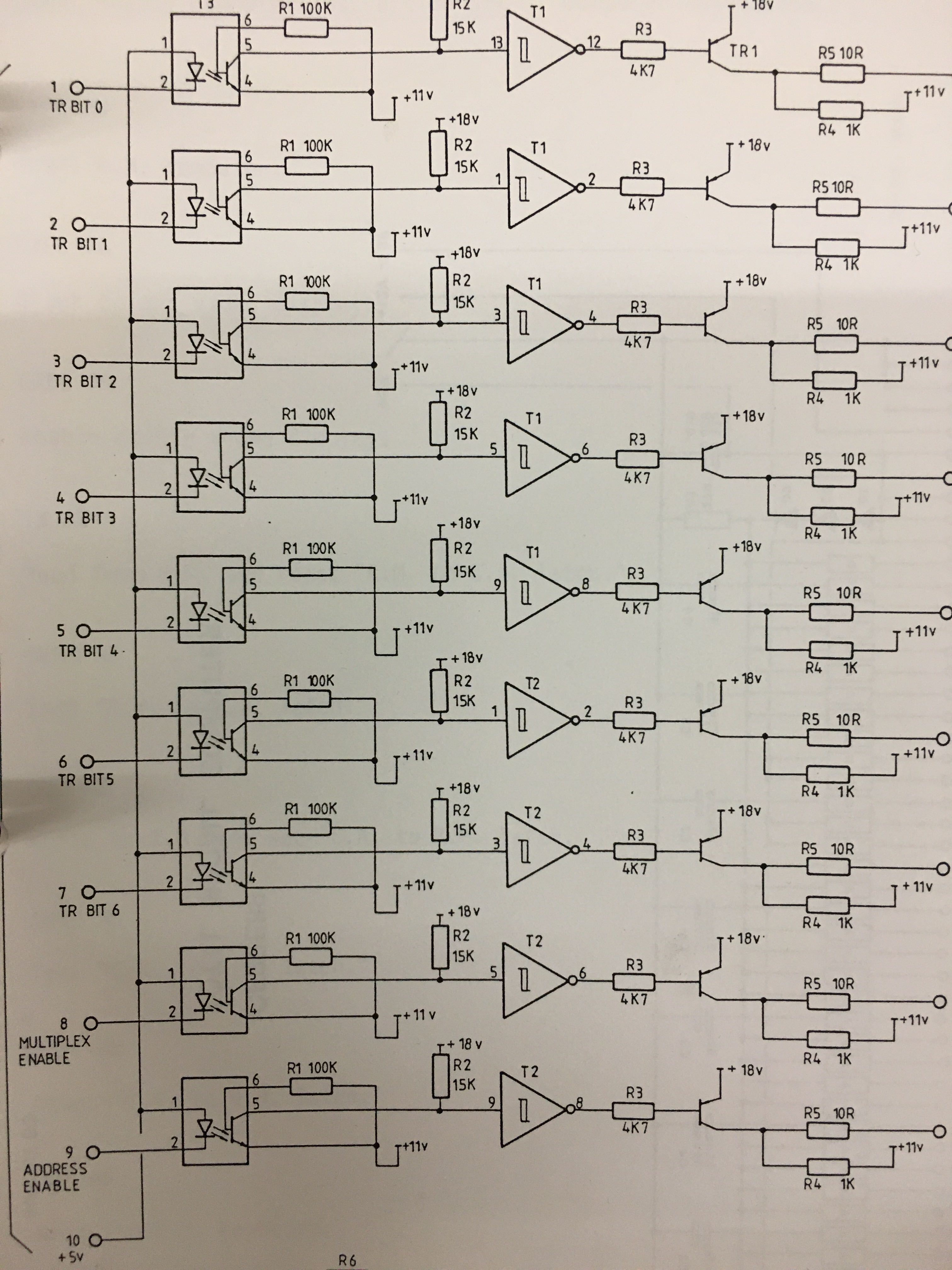
I have attached the (very old 80's) scematics with optocouplers on the left.
They are all fed by the same 5V source, in this case my arduino 5v output.
Now I want to switch them with digital ports on the Arduino, but it's kind of the other way around..
I can set the ports on OUTPUT LOW to make them 'ground' and open up.
But can I set them OUTPUT HIGH without destroying anything?
Or do I have to use INPUT LOW to disconnect it, so switch between output low and input low.
If you have any advice on this.. thank you very much!
You need a resistor between the output pin of the arduino and the input of the optocoupler to limit the current, same as when you are driving an LED with an output pin. Setting the output to HIGH will not damage anything, you would simply be putting 5V on both sides of the LED inside the optocoupler, and there would be no current flow.
With the anodes of all the LEDs inside the optocouplers connected in common to the 5V supply, to turn one of them on you would bring its cathode to ground. That's the way the original circuit worked, and you could replicate that by setting your Arduino pin to OUTPUT, LOW to turn that optocoupler on. To turn it off, you would just bring the pin back to HIGH (still an OUTPUT).
But there's a question about how much current flows through one of those LEDs when it's turned on. You may have to insert a resistor in the line from each Arduino pin to its optocoupler to make sure the current flow isn't excessive. And there may be a problem with the aggregate current the circuit uses. Do you have a link to the optocouplers you will be using? Do you know the maximum number of optocouplers that would ever be turned on at the same time?
I think you seriously need to explain what this circuit is supposed to do. I presume you are trying to resurrect an obsolete piece of equipment; you most certainly would not be building anew using this design!
Clearly you need to use current-limiting resistors between Arduino outputs and the individual optocouplers and you will drive the outputs LOW to enable them. If the anode line is correctly connected to the same 5 V as the Arduino, then when the output is HIGH there is no voltage across the LED so that is no problem. Even for the obsolete 4N25 optocouplers, a 1k resistor will allow sufficient current to drive the LEDs.
Thank you for the quick replies and solid answers.
Indeed it's a very old piece of equipment from the early 80s, the optocouplers send the TR and Enable bits to an array of inhibited multiplexers with together 119 used options. That part is working well.
They are CNY17-1 optocouplers. Reading the specs makes me believe there is no extraneous current drawing, even when all activated at the same time (can be sent in a short single pulse), also the voltages are well within the boundaries, and would need no extra resistors.
Reading your excellent comments make me doubt my own opinion about the resistors though.