Well the reason why I said they have low output impedance is that I've read many sources that show something like this:
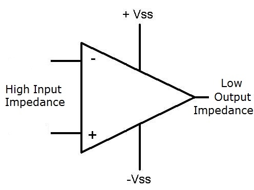
but I guess thats just because of the ideal op amp concept.
Well the reason why I said they have low output impedance is that I've read many sources that show something like this:
but I guess thats just because of the ideal op amp concept.
Yep..... what is important (I reckon) is ...... 'relative'.... relatively low source impedance (or output impedance), compared with the relatively high input impedance of the next stage.
Marciokoko:
but I guess thats just because of the ideal op amp concept.
The ideal op-amp concept is ..... infinite input impedance, and zero source (output) impedance. But if we assume relatively low output impedance, and relatively high input impedance, then that works quite nicely in most cases.
It all goes back to the theory of relativity ![]()
Thanks guys. I starting to get this. Or at least bits and pieces of it.
yep, an ideal op amp would have an output impedance = 0
of course, we are in a real world, and it is not 0, but, even the old 741 has an output impedance of about 75 Ohm .
look at the picture (page 10 of the datasheet Raschemmel posted) : it is less than 100 Ohm

To make sure that the voltage signal drops fully on the op amp, it must have a very high input impedance, so that the voltage drops fully across it. If it had a low input impedance, the voltage may not drop across it and it would not receive the signal. This is why op amps must have high-input impedances.
I never thought of WANTING to have the voltage drop across a device. It may seem silly to many but for me voltage drops are a bad thing. In this case it is being stated that if there is not a large voltage drop across the opamp, the signal (current) will not flow downriver to the speaker.
I guess they meant "we want to fully transfer the voltage......"
the word "drop" is confusing ![]()
alnath:
look at the picture (page 10 of the datasheet Raschemmel posted) : it is less than 100 Ohm
Yeah..... less than about 1 Ohm, below 80 kHz under those particular open loop measurement conditions.
I guess they meant "we want to fully transfer the voltage......"
the word "drop" is confusing
Totally agree.
. less than about 1 Ohm, below 80 kHz under those particular open loop measurement conditions.
And those conditions are not practical to use are they?
Grumpy_Mike:
And those conditions are not practical to use are they?
The assumption of relatively low output impedance relative to the relatively-high input impedance of a following op-amp stage is generally fine. Wasn't me that put up that data sheet stuff. And yes....that data can be practical. They can be linked to the closed loop system.
The assumption of relatively low output impedance relative to the relatively-high input impedance of a following op-amp stage is generally fine. Wasn't me that put up that data sheet stuff.
Was that your answer to the following question ?
And those conditions are not practical to use are they?
Can you rephrase your answer in terms of yes or no ?
ok so without getting too sophisticated, an opamp takes a small voltage and amplifies it. But it generates a power output with very small current, P=I*V[large V but small I]. Compared to the next stage in the case of a mic-speaker circuit, the output impedance of the op amp is very low compared to that of a speaker, which is about 8 Ω or a headphone set which is 32 Ω. The opamp output impedance is usually around 100 Ω, which is too high compared to the 8-32 Ω of audio out. Therefore we must match that impedance such that there is enough current to drive the low impedance audio, R=V/I [larger I gives smaller R]...
Sorry if Im oversimplifying ...
Marciokoko:
ok so without getting too sophisticated, an opamp takes a small voltage and amplifies it. But it generates a power output with very small current, P=I*V[large V but small I]. Compared to the next stage in the case of a mic-speaker circuit, the output impedance of the op amp is very low compared to that of a speaker, which is about 8 Ω or a headphone set which is 32 Ω. The opamp output impedance is usually around 100 Ω, which is too high compared to the 8-32 Ω of audio out. Therefore we must match that impedance such that there is enough current to drive the low impedance audio, R=V/I [larger I gives smaller R]...Sorry if Im oversimplifying ...
I think you're understanding it.
General op-amp circuits usually have relatively small power output capability. It doesn't have enough power to drive headphones...... so an amplifier stage can be added, which can output the required power to drive the headphones.
The impedance 'matching' (in relation to maximum power transfer) is beneficial.... but not always necessary. If the amplifier can output lots of power, then can always keep increasing the output power until you get the desired volume coming out from the headphones. As long as the amplifier doesn't go into voltage 'saturation', then it should be ok. Just note that max power transfer doesn't mean maximum power efficiency..... since half the total power is actually lost on the source side when we're operating at the maximum power transfer condition.
First of all , I think you are misled if you think you would drive an 8 ohm speaker DIRECTLY with an op amp.
You would not.
You would use an audio output transformer
1 k ohm: 8 ohm
1k ohm primary impedance
8 ohm secondary impedance.
This presents an impedance of 1 k ohms to the op amp output stage and an impedance of 8 ohms to the speaker As you already know, an op amp can drive a 1 k ohm impedance.
General op-amp circuits usually have relatively small power output capability. It doesn't have enough power to drive headphones...... so an amplifier stage can be added, which can output the required power to drive the headphones.
The impedance 'matching' (in relation to maximum power transfer) is beneficial.... but not always necessary. If the amplifier can output lots of power, then can always keep increasing the output power until you get the desired volume coming out from the headphones. As long as the amplifier doesn't go into voltage 'saturation', then it should be ok. Just note that max power transfer doesn't mean maximum power efficiency..... since half the total power is actually lost on the source side when we're operating at the maximum power transfer condition.
Is there a point in all this that includes a solution for the OP ?
Marciokoko:
an opamp takes a small voltage and amplifies it.
The reason why I mentioned 'general op amp' has relatively low power output.... is there are op-amps that can easily drive head-phones.
Like... OPA549
OPamp gain - open-loop it's huge, with it's gain-of-one point quoted as the gain-bandwith product. Even for crude amps like the LM324/358 it's > 1MHz. At 1kHz this gain will be >1000. There are far better devices around these days, and plenty of specially designed power audio amps. Unless you want to do your own... I did this for Cambridge Audio years ago.
Once you close the loop with feedback and reduce the gain to - say - 10 times - one of the effects is to reduce the apparent output impedance by the excess gain - in this case 100x. But that doesn't affect the maximum current
the device can deliver, nor how near it can swing to either supply rail.
A great hero of mine was a principal scientist at National semiconductor, who build many high quality
analog gadgets - Bob Pease. ( They've just been taken over by Texas Intruments (TI) ). I even met him once.
Google 'Bob Pease' for a great series of columns written by him over many years. for 'Analog Design' magazine. - they'll teach you more than us mere forum writers ( well at least me) could ever do
regards
Allan
allanhurst:
Google 'Bob Pease' for a great series of columns written by him over many years. for 'Analog Design' magazine.
Will do. You're lucky to have met him. Sounds like a great person.
Googled and found him. Ill read up tonite. Im worried itll be over my head though. Im still trying to understand simple things like impedance, opamps that increase voltage but not current, transistors that increase current but not voltage...
all because i decided to take up a hobby! ![]()
Yeah, I remember reading Bob Pease articles years ago in EDN (or was it Electronics Design?) - one of the major trade journals. National Semi had a number of cool folks - remember John Abbot ? They used humor in some of their data books too - I remember one buffer was listed as having a bandwidth of "DC to Daylight" ![]() But, the Bob Pease articles are definitely worth a read - a little dated perhaps, but still an excellent source of information.
But, the Bob Pease articles are definitely worth a read - a little dated perhaps, but still an excellent source of information.
Southpark:
The assumption of relatively low output impedance relative to the relatively-high input impedance of a following op-amp stage is generally fine. Wasn't me that put up that data sheet stuff. And yes....that data can be practical. They can be linked to the closed loop system.
yep, it was me ![]()
And closed loop output impedance is even lower :
SBOA092A
HANDBOOK OF OPERATIONAL AMPLIFIER APPLICATIONS
Closed Loop Impedance Levels
Open loop output impedances are given in the specifications and range from 3 Ω to 5000 Ω, with
the majority of operational amplifiers having 100 or 200 Ω open loop output impedance. Since
the input and feedback resistors usually will vary from 1 kΩ to 1 MΩ, this may represent a rather
poor approximation of the ideal zero output impedance. However, as we shall see, the equivalent closed loop output impedance is typically less than an ohm.
Open loop input impedances are also specified and run as high as 10^15Ω. Compared to the
typical feedback impedance levels, this can be a very good approximation of the ideally infinite,
open loop input impedance. Practically, this is of little importance since the input resistor
determines the closed loop input impedance of the inverting amplifier. Calculations will show
that the equivalent input impedance of the non-inverting amplifier may be hundreds or thousands of MΩ, closed loop.
.....
......
More general calculations would show that the output impedance is reduced by the loop gain.
The voltage follower is a limiting case in which the loop gain is equal to the open loop gain.
page 42 of Handbook of operational amplifiers (Ti)
Nice info alnath! Thanks for putting up that handbook link.
raschemmel:
First of all , I think you are misled if you think you would drive an 8 ohm speaker DIRECTLY with an op amp.You would not.
You would use an audio output transformer
1 k ohm: 8 ohm
1k ohm primary impedance
8 ohm secondary impedance.This presents an impedance of 1 k ohms to the op amp output stage and an impedance of 8 ohms to the speaker As you already know, an op amp can drive a 1 k ohm impedance.
Is there a point in all this that includes a solution for the OP ?
I don't think audio output transformers have been used since the days of thermionic
valves, they introduce a lot of distortion and reduce the output voltage below what you need
for reasonable output powers in semiconductor circuits - and they cost more than an semiconductor
power amplifier chip.
What you would probably do is drive a class-D amplifier chip with the opamp!
All power electronics these days is switched, its almost a fact of life...