I have old analytic scale (Sauter ar 1014) and I have hard time figuring out correct pinout for RS232. It doesn't have any manual with it and can't find one from internet.
So my questions are:
Is Din5 connector to dsub9 connector always the same?
Should I first connect it with pc, and try to figure out baudrate etc, or directly to arduino with max3232 chip?
What are those orange green black connectors?
I don't think so. The DIN connector isn't standard for RS-232.
Even the DB9 wiring isn't completely standardized. There is DTE and DCE where the RX, TX, and handshaking are switched-around. I don't know which way a standard computer port is wired but if you want to connect two computers together you can't have TX to TX so there are null-modem cables or null-modem adapters to crisscross the connections.
And the handshaking is not always used.
"Real" RS-232 uses positive & negative voltages. There are converter chips like the MAX232 but if your scale/balance is 5V and you are interfacing with a 5V Arduino, that's not necessary... You'd need converters on both ends and that would be silly...
If it is RS232 and meets the standard Tx will be a -3 to a -25 volts. Rx is positive and generally around 3-9 volts. These are just rules of thumb, no warranty of accuracy.
Okay,
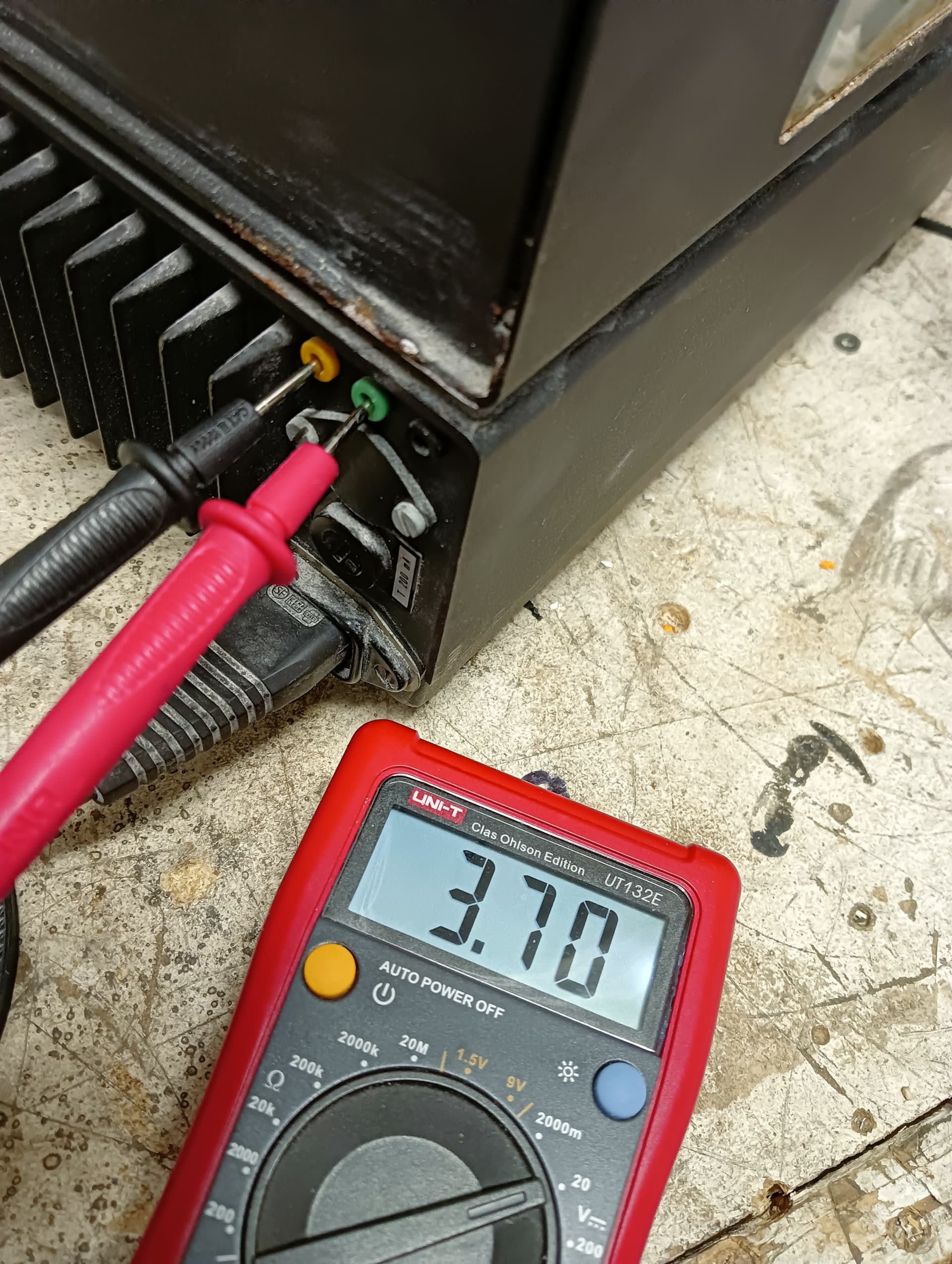
I can't seem to get any input from scale. Is the scale broken as all the pins (except ground) are constantly 5 volts?
my code:
#include <LiquidCrystal_I2C.h>
 LiquidCrystal_I2C lcd(0x27, 16, 2); // Creates I2C LCD Object With (Address=0x27, Cols=16, Rows=2)


int incomingByte = 0; // for incoming serial data

    void setup() {
      Serial.begin(9600); // opens serial port, sets data rate to 9600 bps
      lcd.init();
  lcd.backlight();
  lcd.setCursor(0, 0);


    }

    void loop() {


      // send data only when you receive data:
      if (Serial.available() > 0) {
        // read the incoming byte:
        incomingByte = Serial.read();

        // say what you got:
        lcd.print(incomingByte);

      }
    }
I do not know how to get data to show up on serial monitor or in the lcd.
Next step is making din5 to dsub9 cable and trying with pc. Then logic analyzer. But I don't know if there is any analyzing if all pins are constantly 5 volts.
Perhaps heading off on a tangent here, but it looks like your scales are fairly old, so out of any warranty etc. Without access to the exact user manual for the scales, it may save a lot of effort and guessing if you were to remove the cover and examine the internals to determine if the device has any serial output capability. Look for an RS232 (most likely) line driver chip and then where it connects to externally.
EDIT: I see that there may be mains voltages present inside so make sure that the scales are unplugged first before removing any covers.